


43
CHAPTER 3 SPECIFICATIONS
3
3.5 Specifications of I/O Interfaces with External Devices
3.5.3 List of I/O signal details
3.5.3 List of I/O signal details
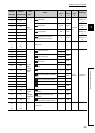
This section describes details of signals that are input or output through external device connectors on the QD73A1.
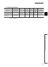
Signal name
Connector
name
Pin
number
Signal detail
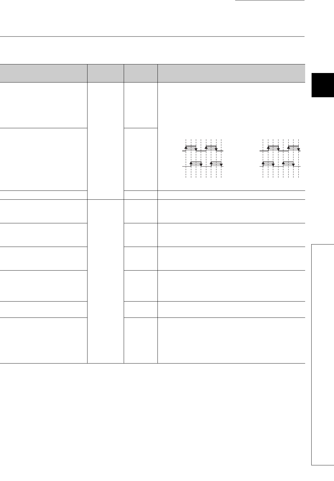
Phase-A feedback pulse (PULSE A)
(+ side)
Phase-B feedback pulse (PULSE B)
(+ side)
Phase-Z feedback pulse (PULSE Z)
(+ side)
SERVO
13
5
6
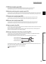
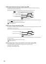
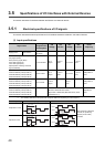
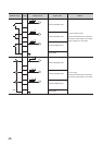
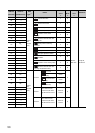
• Feedback pulse signals of encoder's phases A, B, and Z are
input.
• When the phase A leads the phase B, the positioning address
increases at the rising and falling edges of each phase.
• When the phase B leads the phase A, the positioning address
decreases at the rising and falling edges of each phase.
Phase-A feedback pulse (PULSE A)
(- side)
Phase-B feedback pulse (PULSE B)
(- side)
Phase-Z feedback pulse (PULSE Z)
(- side)
11
10
7
Analog GND 9
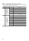
Upper limit signal (FLS)
CONT.
7
• This signal is input from the limit switch placed at stroke upper
limit position.
• As this signal turns off, positioning stops.
Lower limit signal (RLS) 6
• This signal is input from the limit switch placed at stroke lower
limit position.
• As this signal turns off, positioning stops.
Near-point dog signal (DOG) 1
• This signal is used for detection on the near-point dog during
OPR.
• As the near-point dog turns on, this signal is detected.
Stop signal (STOP) 9
• Input this signal to stop positioning.
• As this signal is turned on, the QD73A1 cancels the positioning
in execution. Once this signal was turned on, the operation
does not restart even if this signal is turned off.
Speed-position switching command
signal (CHANGE)
8
Input this signal to switch control during the speed-position control
switch mode.
Power supply (5 to 24V) 5
This power supply is common to the following signals.
• Upper limit signal (FLS)
• Lower limit signal (RLS)
• Near-point dog signal (DOG)
• Stop signal (STOP)
• Speed-position switching command signal (CHANGE)
Phase A
Phase B
Positioning
address +1+1+1+1+1+1+1+1
[When increased]
Phase A
Phase B
Positioning
address -1 -1 -1 -1 -1 -1 -1 -1
[When decreased]