45
CHAPTER 3 SPECIFICATIONS
3
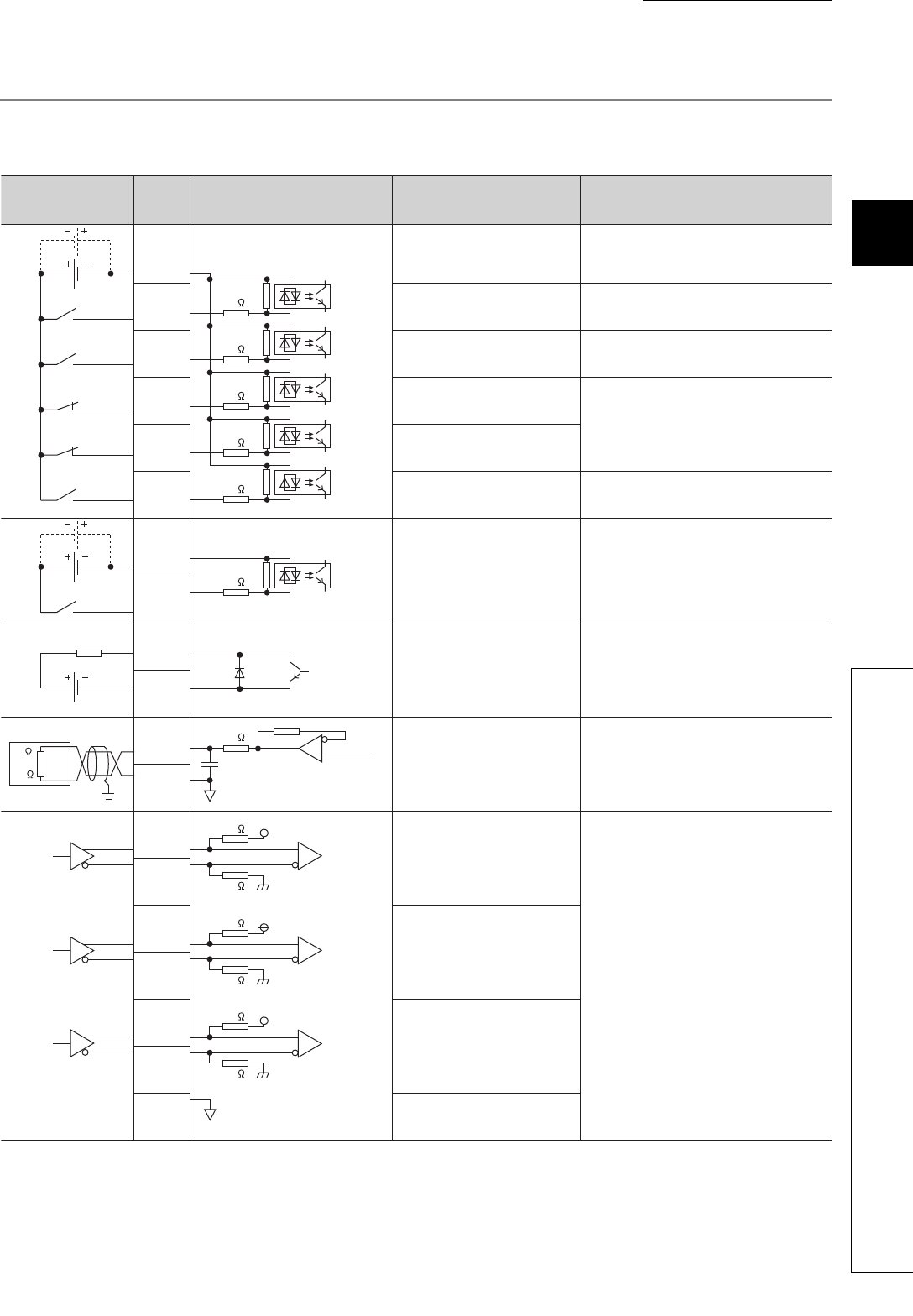
3.5 Specifications of I/O Interfaces with External Devices
3.5.4 I/O interface internal circuit
3.5.4 I/O interface internal circuit
This section shows internal circuits of external device interfaces on the QD73A1 in schematic diagrams.
*1 When input impedance of the servo amplifier is low, analog output level may become low due to this resistance. If that
causes a problem, perform gain adjustment again with the servo amplifier being connected.
24VDC
5VDC
24VDC
5VDC
Pin No. Internal circuitExternal wiring Signal name Remark
Power supply
Near-point dog signal (DOG)
Stop signal (STOP)
Upper limit signal (FLS)
Lower limit signal (RLS)
Speed-position switching
command signal (CHANGE)
Servo READY signal
(READY)
Servo ON signal (SVON)
Speed command signal
Phase-A feedback pulse
Phase-B feedback pulse
Phase-Z feedback pulse
Analog GND
Input a voltage of 5 to 24VDC.
-
-
If not using these signals, keep them on.
-
-
-
-
[For differential input]
Connect these terminals to the terminal/
connector for pulse output of an encoder.
Load
Load
Servomotor, module,
or others
2.4k
1k
5V
0V
1k
1k
5V
1k
1k
5V
1k
1k
1M
2.4k
2.4k
2.4k
2.4k
2.4k
47
0V (analog GND)
*1
5
1
9
7
6
8
1
2
3
4
15
14
13
11
5
10
6
7
9
5 to 24VDC
to
SN75115


