264
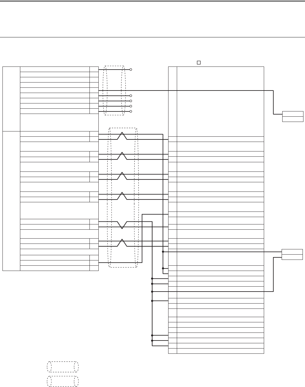
Appendix 2 Connection Examples
Appendix 2.1 Example of connection with a servo amplifier
manufactured by Mitsubishi Electric Corporation
(1) Connection with MR-J3A (Differential driver)
*1 indicates use of shielded cables. Use shielded cables for wiring.
*2 indicates use of shielded twisted pair cables. Use shielded twisted pair cables for wiring.
CONT.
connector
SERVO
connector
DOG Near-point dog signal
QD73A1
N.C.
N.C.
N.C.
Power supply (5 to 24V)
RLS Lower limit signal
FLS Upper limit signal
CHANGE Speed-position switching command signal
STOP Stop signal
1
2
3
4
5
6
7
8
9
1
2
13
11
5
10
6
7
4
3
15
14
8
9
12
49
4
5
6
7
8
9
34
15
2
3
20
21
46
47
17
18
28
30
43
42
44
READY Servo READY signal (+ side)
READY Servo READY signal (- side)
PULSE A Phase-A feedback pulse (+ side)
PULSE A Phase-A feedback pulse (- side)
PULSE B Phase-B feedback pulse (+ side)
PULSE B Phase-B feedback pulse (- side)
PULSE Z Phase-Z feedback pulse (+ side)
PULSE Z Phase-Z feedback pulse (- side)
SVON Servo ON signal (- side)
SVON Servo ON signal (+ side)
Speed command signal (+ side)
Speed command signal (- side)
N.C.
Analog GND
N.C.
RD Ready
LA Encoder A-phase pulse (differential line driver)
LAR Encoder A-phase pulse (differential line driver)
LB Encoder B-phase pulse (differential line driver)
LBR Encoder B-phase pulse (differential line driver)
LZ Encoder Z-phase pulse (differential line driver)
LZR Encoder Z-phase pulse (differential line driver)
LG Control common
SON Servo-on
VC Analog speed command
LG Control common
DICOM Digital I/F power supply input
DICOM Digital I/F power supply input
DOCOM Digital I/F common
DOCOM Digital I/F common
ST1 Forward rotation start
ST2 Reverse rotation start
LG Control common
LG Control common
EMG Emergency stop
LSP Forward rotation stroke end
LSN Reverse rotation stroke end
External
power supply
24V
0V
External
power supply
24V
0V
*1
*2
CN1 MR-J3- A


