75
CHAPTER 5 DATA USED FOR POSITIONING
5
5.2 Positioning Parameters
5.2 Positioning Parameters
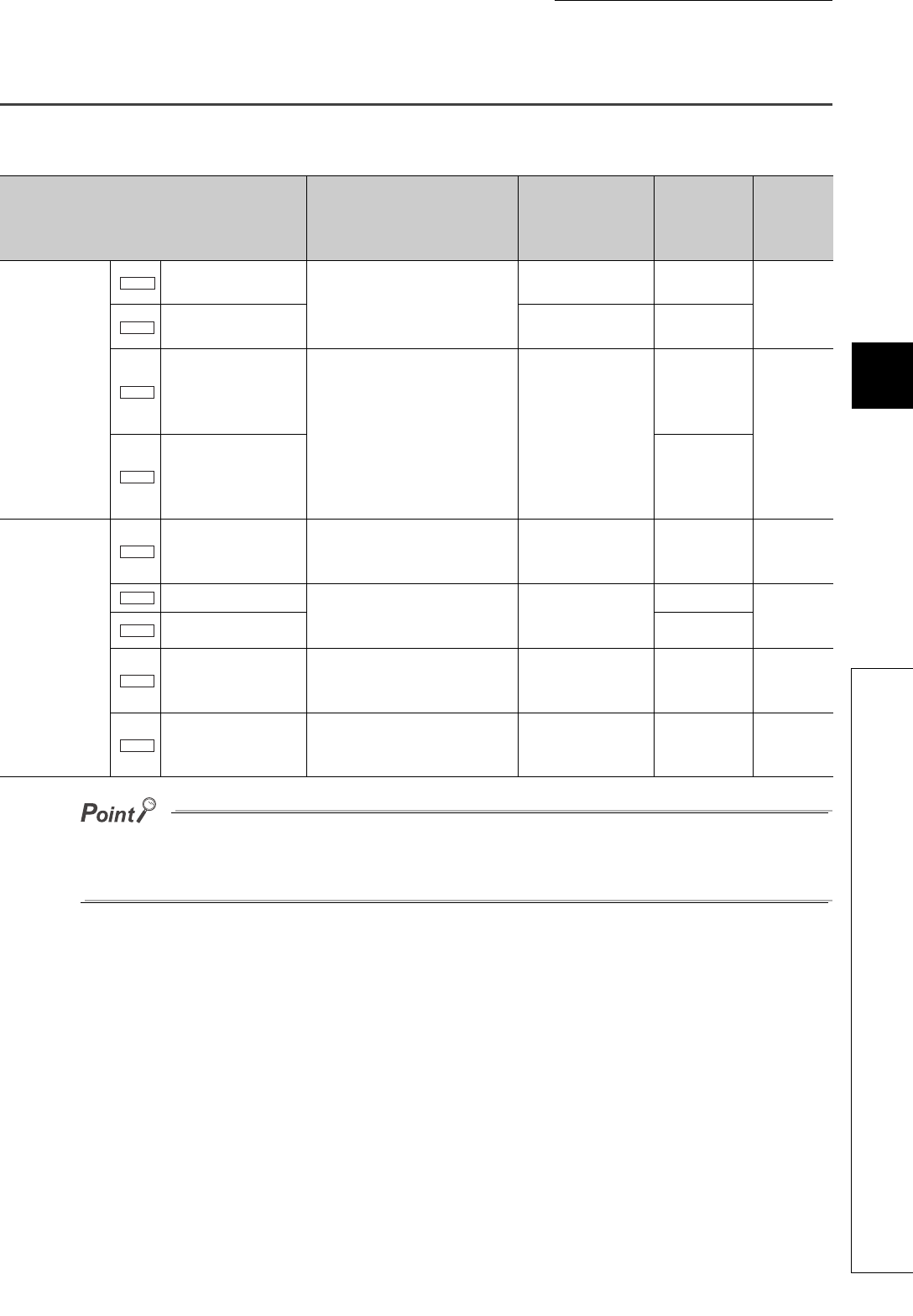
This section describes the details of positioning parameters.
● The set data of fixed parameters are activated when PLC READY signal (Y2D) is turned on, and the error check is
executed at the same time.
● Variable parameters can be set any time, but the error check is executed when a start signal is turned on.
Item Setting range Default value
Buffer
memory
address
(decimal)
Reference
Fixed
parameter
Stroke limit upper limit
-2147483648 to
2147483647pulse
2147483647pulse
0
1
Page 76,
Section
5.2 (1)
Stroke limit lower limit 0pulse
2
3
Numerator of
command pulse
multiplication for
electronic gear (CMX)
1 to 9999
(Satisfy the following condition.
1/50 CMX/CDV 50)
1
4
Page 77,
Section
5.2 (2)
Denominator of
command pulse
multiplication for
electronic gear (CDV)
5
Variable
parameter
Speed limit value
10 to 4000000pulse/s
(Set in the unit of 10pulse/s.)
200000pulse/s
20
21
Page 77,
Section
5.2 (3)
Acceleration time
2 to 9999ms 300ms
22
Page 78,
Section
5.2 (4)
Deceleration time 23
In-position range 1 to 20479pulse 5pulse 24
Page 78,
Section
5.2 (5)
Positioning mode
0: Position control mode
1: Speed-position control switch
mode
0: Position control
mode
25
Page 78,
Section
5.2 (6)
Pr.1
Pr.2
Pr.3
Pr.4
Pr.5
Pr.6
Pr.7
Pr.8
Pr.9


