


3 - 42
MELSEC-
A
3 SPECIFICATIONS AND FUNCTIONS
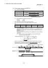
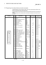
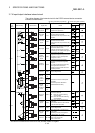
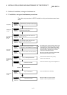
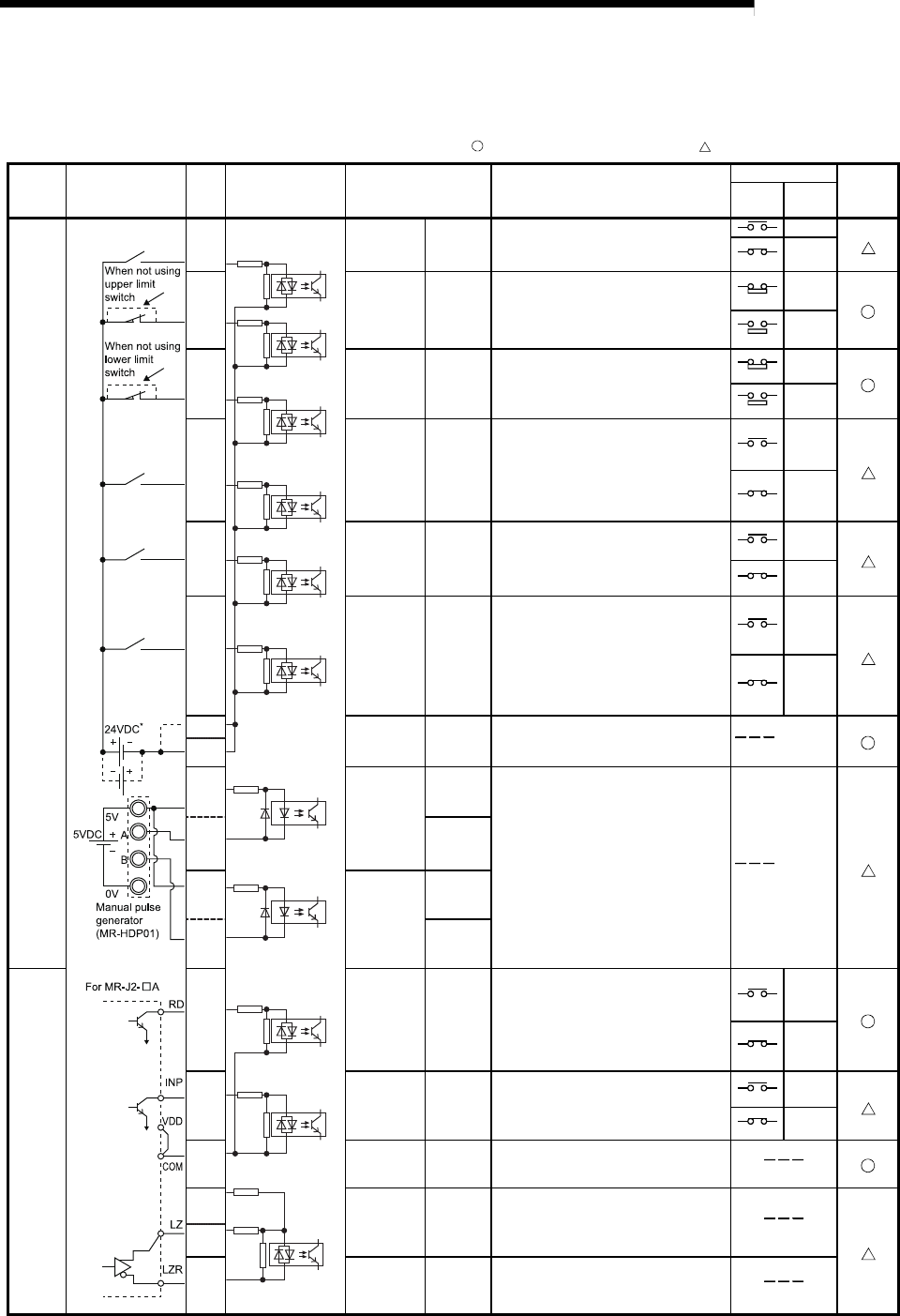
3.7.4 Input/output interface internal circuit
The outline diagram of the internal circuit for the D75P2 external device connection
interface is shown below.
: Wiring is necessary in positioning. : Perform wiring when necessary.
Input/out
-put
class
External wiring
Pin
No.
Internal circuit Signal name Details
ON/OFF status
Need for
wiring
External
wiring
D75P2
Input
11
Near-point
dog signal
DOG
• Near-point dog detection signal for a
machine zero point return
OFF
ON
12
Upper limit
signal
FLS
• Signal for the limit switch provided at
the upper limit of the stroke.
• Also used for the zero point return retry
function.
ON
OFF
(STOP)
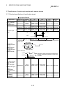
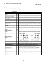
13
Lower limit
signal
RLS
• Signal for the limit switch provided at
the lower limit of the stroke.
• Also used for the zero point return retry
function.
ON
OFF
(STOP)
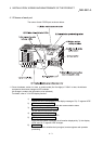
14 Stop signal STOP
• Signal that stops positioning externally
• When stopping positioning, this signal
turns ON in 4ms or more.
• After this signal has been turned ON,
positioning is not restarted if this signal
is turned from ON to OFF.
OFF
ON
(STOP)
15
Speed/
position
changeover
signal
CHG
• Signal that changes from speed control
to position control in speed/position
changeover control.
OFF
ON
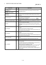
16
External
start signal
STRT
• Signal that performs an external
positioning start/speed change/skip
request.
• To make an external start valid, keep
this signal ON more than 4ms.
• Set which function will be used in the
detailed parameter.
OFF
ON
35
Common COM • Input voltage 24VDC.
36
(+)
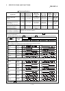
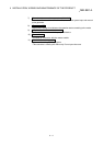
9
Manual
pulse
generator A
phase
PULSER
A+
• Terminal to connect a manual pulse
generator.
• Introduced product: MR-HDP01
(Mitsubishi Electric make)
(–)
27
PULSER
A–
(+)
10
Manual
pulse
generator B
phase
PULSER
B+
(–)
28
PULSER
B–
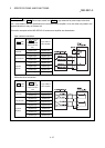
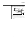
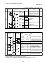
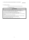
Input
7
Drive unit
READY
READY
Signal for judging whether the drive unit
is normal or abnormal.
ON : Drive unit normal. Positioning
control enabled.
OFF : Drive unit abnormal. Positioning
control disabled.
OFF
ON
8
In-position
signal
INPS
• Enter the in-position signal from the
drive unit.
• The ON/OFF status can be monitored
with the remote input (RX).
OFF
ON
26 Common COM • Input voltage 24VDC.
6
Zero point
signal
PG0
• Zero point signal for a machine zero
point return.
• Generally, the zero point signal of a
pulse encoder, etc. is used.
24
25 Common PG0 COM
Input voltage 24V/15V/5VDC
Pin No. 6-25 24V/15VDC
Pin No. 24-25 5VDC
* The terminal connected to the common line may be either positive or negative.