


6 - 14
MELSEC-
A
6 SEQUENCE PROGRAM USED FOR POSITIONING CONTROL
*
1
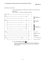
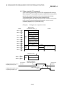
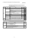
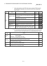
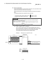
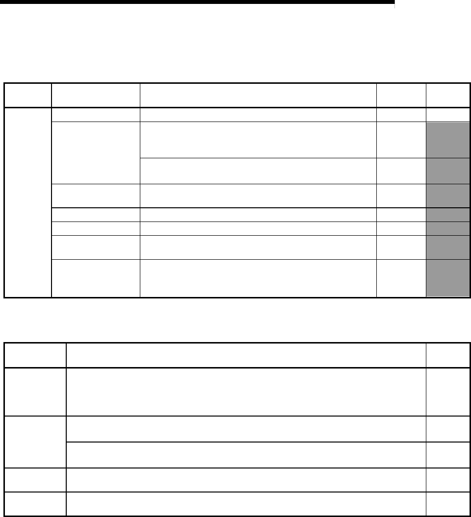
When reading data from the D75P2 buffer memory using the FROM command,
the control data is designated in the transmission buffer of the corresponding
master module.
Designated
data
Item Details
Setting
range
Setting
side
Control
data
Dummy area – – System
Station No., request
code
Station No. (designate with high-order bytes (bits 8 to 15))
Designate the station No. of the intelligent device station to
be accessed.
0 to 64 User
Request code (designate with low-order bytes (bits 0 to 7))
Designate the read request code.
10
H User
Transmission buffer
write data size (byte)
(Fixed value) 8
User
Quantity (Fixed value) 1 User
Access code, attribute (Fixed value) 0004H User
Buffer memory
address
Designate the head address (0H or higher) of the buffer
memory.
0H to 17D4H User
No. of read points
(word)
Designate the data size (No. of words) to be written in so that
the D75P2 buffer memory address 17DD
H is not exceeded.
17DD
H
(buffer memory address -1) + No. of read points
1 to 480
User
*
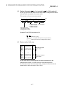
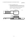
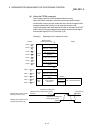
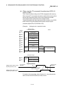
2
The same details as the data read from the D75P2 buffer memory with the FROM
command is stored in the reception buffer of the corresponding master module.
Designated
data
Details
Setting
side
Complete
status
The status when the command is completed is stored.
0 : Normal completion
Other than 0 : Error completion (error code)
Refer to the CC-Link Master Module User's Manual.
System
Station No.,
request code
Station No. (designate with high-order bytes (bits 8 to 15))
The station No. of the accessed intelligent device station is stored.
System
Request code (designate with low-order bytes (bits 0 to 7))
The read request code (10
H) is stored.
System
Read data size
(byte)
The total No. of bytes of the read data is stored. System
Read data
(byte)
The target D75P2 buffer memory data designated with the control data buffer memory
address items and No. of read points is stored.
System