


3 - 39
MELSEC-
A
3 SPECIFICATIONS AND FUNCTIONS
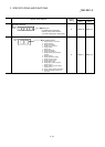
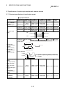
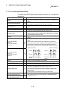
3.7.3 List of input/output signal details
The details of each D75P2 external device connection connector (for 1 axis) signal are
shown below.
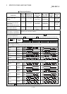
Signal name Pin No. Signal details
Common
36
35
Signal that indicates that transmission data is ready in the ABS transfer
mode.
ABS transmission data READY 34
Common for near-point dog signal, upper/lower limit, stop signal,
speed/position changeover signal, and external start signal.
Common (ABS IN) 33
Common for ABS data bit 0, ABS data bit 1 and ABS transmission data
READY.
Common (ABS OUT) 32
Common for servo ON, ABS transfer mode and ABS request.
ABS request 31
Signal that requests ABS data during ABS transfer mode.
ABS transfer mode 30
Used to select the ABS transfer mode.
While this signal is ON, the "ABS data bit 0", "ABS data bit 1" and "ABS
send data READY" signals are valid.
Servo ON 29
Signal that powers on the base circuit of the servo to make it ready to
operate.
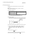
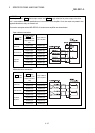
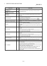
Manual pulse generator
(B phase –)
Manual pulse generator
(A phase –)
28
27
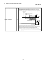
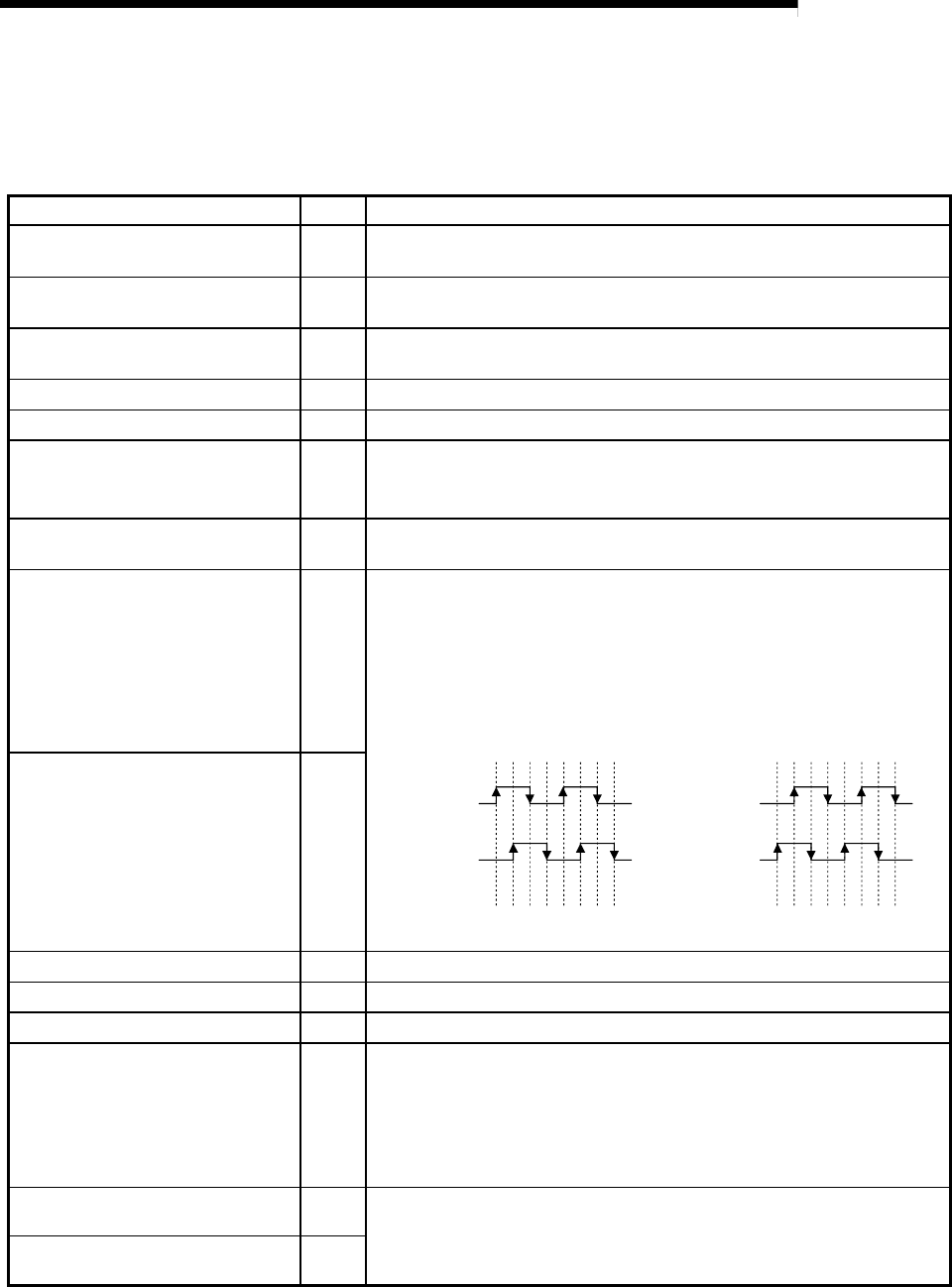
Input the pulse signal from the manual pulse generator A phase and B
phase.
If the A phase is advanced more than the B phase, the positioning
address will increase at the rising edge and falling edge of each phase.
If the B phase is advanced more than the A phase, the positioning
address will decrease at the rising edge and falling edge of each phase.
[When increased] [When decreased]
+1+1+1+1+1+1+1+1 -1 -1 -1 -1 -1 -1 -1 -1
A phase
B phase
Positioning
address
A phase
B phase
Positioning
address
Manual pulse generator
(B phase +)
Manual pulse generator
(A phase +)
10
9
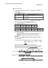
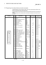
Common 26
Common for drive unit READY and in-position.
Deviation counter clear common 23
Common for deviation counter clear.
Zero point signal common 25
Common for zero point signal (+5V) and zero point signal (+24V).
Zero point signal (+5V)
Zero point signal (+24V)
24
6
Input the zero point signal for machine zero point return.
Use the zero point signal of the pulse encoder or the like.
Use this signal when the zero point return method is the stopper stop
method and the machine zero point return complete is input from an
external source.
The zero point signal is detected at turning from OFF to ON.
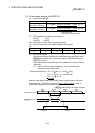
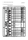
Pulse sign
Pulse output (differential driver –)
22
21
Output the positioning pulses and pulse sign for the differential driver
compatible drive unit.
Pulse sign
Pulse output (differential driver +)
4
3