3 - 32
MELSEC-
3 SPECIFICATIONS AND FUNCTIONS
3.6 Transmission delay time
This section indicates the transmission delay time (time required until data is
transmitted).
Cyclic transmission (Common to AJ61BT11, A1SJ61BT11, AJ61QBT11,
A1SJ61QBT11 and QJ61BT11N)
(1) Calculation expression
Details Calculation expression (Unit: ms)
Master module (RY/RWw) D75P2
(RY/RWw)
SM + LS
3 + 1.6 (internal processing time)
Master module (RX/RWr) D75P2
(RX/RWr)
SM : Scan time of master module sequence program
LS : Link scan time (refer to the Master Module User's Manual)
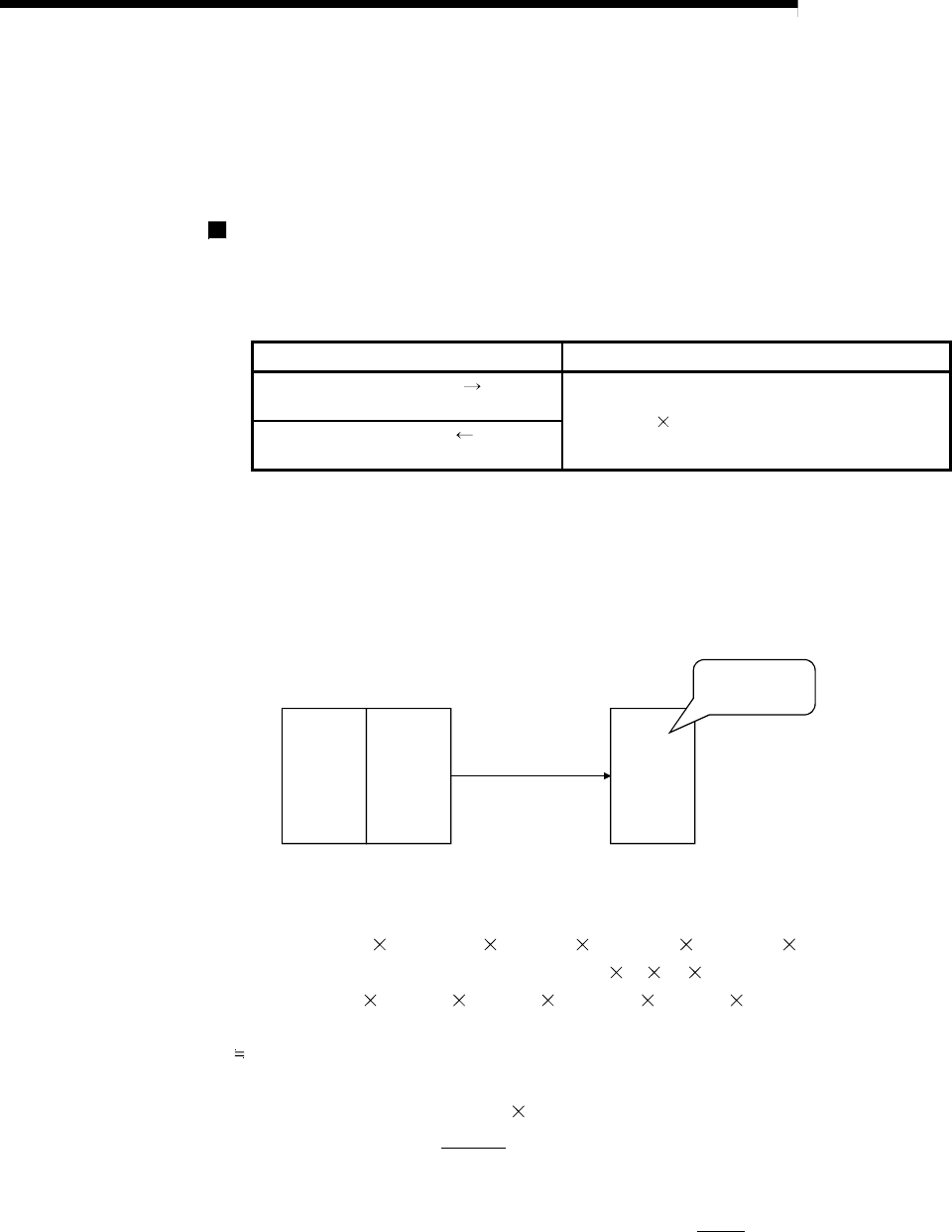
(2) Calculation example
The following example calculates the time from when the positioning start signal
(RY(n+1)0, RY(n+1)1) is turned ON until the D75P2 starts positioning operation.
D75P2
PLC CPU
Master
module
RY(n+1)0,
RY(n+1)0 is turned
ON.
Positioning
operation start!
When SM is 20ms, transmission speed is 10Mbps, and only one D75P2 is connected
LS = BT{29.4 + (NI 4.8) + (NW 9.6) + (N 32.4) + (ni 4.8) + (nw 9.6)} + ST +
{number of communication error stations
48 BT number of retries}
= 0.8{29.4 + (8
4.8) + (8 9.6) + (1 32.4) + (4 4.8) + (4 9.6)} + 1600 + 0
= 1787.68μs
1.8ms
Transmission delay time = 20 + 1.8 3 + 1.6
= 27[ms]
Therefore, the time from when the positioning start signal (RY(n+1)0, RY(n+1)1) is
turned ON until the D75P2 starts positioning operation is 27ms.


