5 - 22
MELSEC-
A
5 DATA USED FOR POSITIONING CONTROL
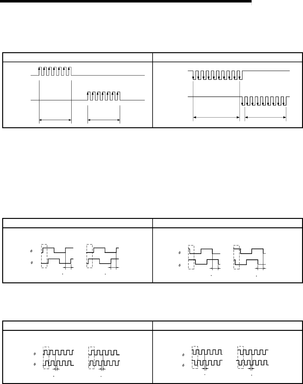
(2) CW/CCW mode
During forward run, the forward run feed pulse (PULSE F) will be output.
During reverse run, the reverse run feed pulse (PULSE R) will be output.
Positive logic Negative logic
PULSE F
PULSE R
Forward run Reverse run
PULSE F
PULSE R
Forward run Reverse run
(3) A phase/B phase mode
Forward run and reverse run are controlled with the phase difference of the A
phase (A) and B phase (B).
When the B phase is 90
°
behind the A phase, the motor will forward run.
When the B phase is 90
°
ahead of the A phase, the motor will reverse run.
The D75P2 defines a waveform having four edges (rising/falling) in one command
pulse as “multiple of 4”, and one having a single edge (rising/falling) in one
command pulse as “multiple of 1”.
(a) For multiple of 1 setting
Positive logic Negative logic
A
phase
(A )
B phase
(B )
Forward run
Forward rotation when one
command pulse is output
Reverse run
Forward rotation when one
command pulse is output
When B phase is
90 behind A
p
hase
When B phase is
90 ahead A
p
has
e
Forward run
Forward rotation when one
command pulse is output
Reverse run
Forward rotation when one
command pulse is output
A phase
(A )
B phase
(B )
When B phase is
90 behind A phase
When B phase is
90 ahead A phase
Example) When one command pulse is output at 1 pulse/s, rising and falling
occur once per second.
(b) For multiple of 4 setting
Positive logic Negative logic
Forward run
When B phase is
90 behind A phase
A phase
(A )
B phase
(B )
Reverse run
When B phase is
90 ahead A phase
Forward rotation when one
command pulse is output
Forward rotation when one
command pulse is output
Forward run Reverse run
Forward rotation when one
command pulse is output
Forward rotation when one
command pulse is output
A phase
(A )
B phase
(B )
When B phase is
90 behind A phase
When B phase is
90 ahead A phase
Example) When one command pulse is output at 1 pulse/s, rising and falling
occur four times per second.


