


5 - 42
MELSEC-
A
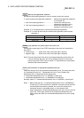
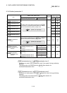
5 DATA USED FOR POSITIONING CONTROL
Item
Setting value, setting range
Default
value
Setting value buffer
memory address
Value set with peripheral
device
Value set with sequence
program
Axis 1 Axis 2
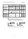
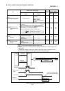
Pr.41
Positioning complete
signal output time
0 to 65535 (ms)
0 to 65535 (ms)
0 to 32767 :
Set as a decimal
32768 to 65535:
Convert into hexadecimal
and set
300 59 209
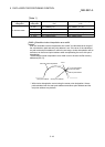
Pr.42
Allowable circular
interpolation error
width
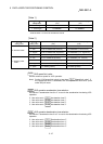
The setting value range differs depending on the "
Pr.1
Unit setting".
(When the stepping motor is used, circular interpolation
control cannot be performed. Set "
Pr.11
Stepping motor
mode selection" to "0: Standard mode".)
Here, the value within the [Table 1] range is set.
[Table 1] on right page
100
60
61
210
211
Pr.43
External start function
selection
0 : External positioning start 0
0 62 212
1 : External speed change
request
1
2 : Skip request 2
Pr.44
Near pass mode
selection for path
control
0 : Positioning address pass
mode
0
0 66 216
1 : Near pass mode 1
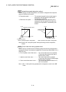
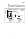
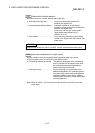
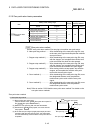
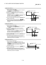
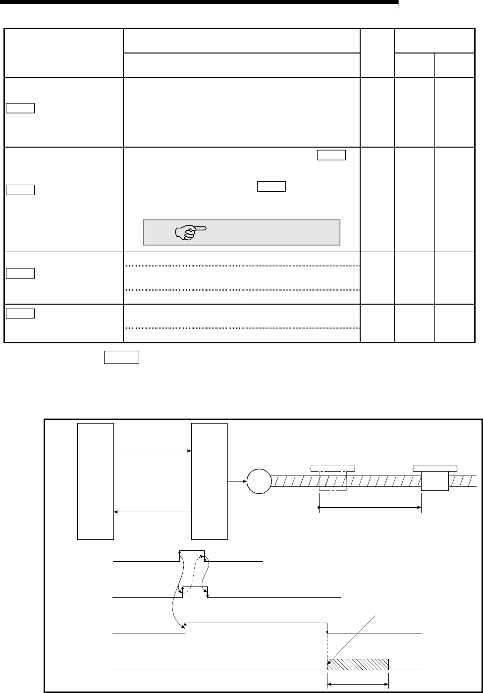
Pr.41
Positioning complete signal output time
Set the output time of the positioning complete signal [RXn7, RXn8] output from
the D75P2.
Positioning complete refers to the state in which the output of pulses from the
D75P2 has completed, and the specified dwell time has passed.
M
D75P2
[RY(n+1)0, RY(n+1)1]
Master
module
Positioning
start signal
Positioning
complete signal
[RXn7, RXn8]
Positioning
Positioning
start signal
Start complete
signal
BUSY signal
Positioning
complete signal
Positioning complete signal
(after dwell time has passed)
Output time
Positioning complete signal output time