


Appendix - 33
MELSEC-
A
APPENDICES
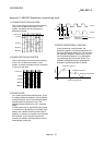
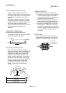
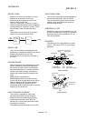
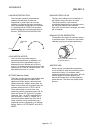
DROOP PULSE
Because of inertia in the machine, it will lag
behind and not be able to track if the
positioning module speed commands are
issued in their normal state.
Thus, for a servomotor, a method is used in
which the speed command pulses are delayed
by accumulation in a deviation counter. These
accumulated pulses are called the droop
pulse.
The deviation counter emits all pulses and
returns to 0 when the machine stops.
1,000
pulses
200 pulses
accumulate
in the
counter
800
pulses
VoltageD/A
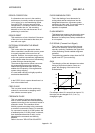
DWELL TIME
This is the time taken immediately after the
positioning is completed to adjust for the droop
pulses in the deviation counter. The
positioning will not be accurate if this time is
too short.
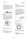
DYNAMIC BRAKE
When protection circuits operate due to power
failures, emergency stops (EMG signal) etc.,
this function is used to short-circuit between
servomotor terminals via a resistor, thermally
consume the rotation energy, and cause a
sudden stop without allowing coasting of the
motor.
Braking power is generated by
electromagnetic brakes only when running
motors with which a large brake torque can be
obtained. Because electromagnetic brakes
have no holding power, they are used in
combination with mechanical brakes to prevent
dropping of the vertical axis.
ELECTROMAGNETIC BRAKE
This function is supplied on motors with
electromagnetic brakes. Electromagnetic
brakes are used to prevent slipping during
power failures and faults when driving a
vertical axis, or as a protective function when
the machine is stopped.
These brakes are activated when not excited.
ELECTRONIC GEAR
This function electrically increases/decreases
the command pulses No. from the D75P2.
Thus, the positioning speed and movement
amount can be controlled by the electronic
gear ratio magnification.
EMERGENCY STOP
Emergency stops cannot be carried out by the
D75P2, so a method of shutting OFF the servo
side power supply from outside the PLC, etc.,
must be considered.
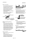
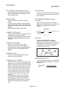
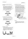
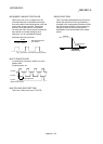
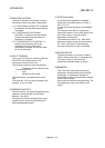
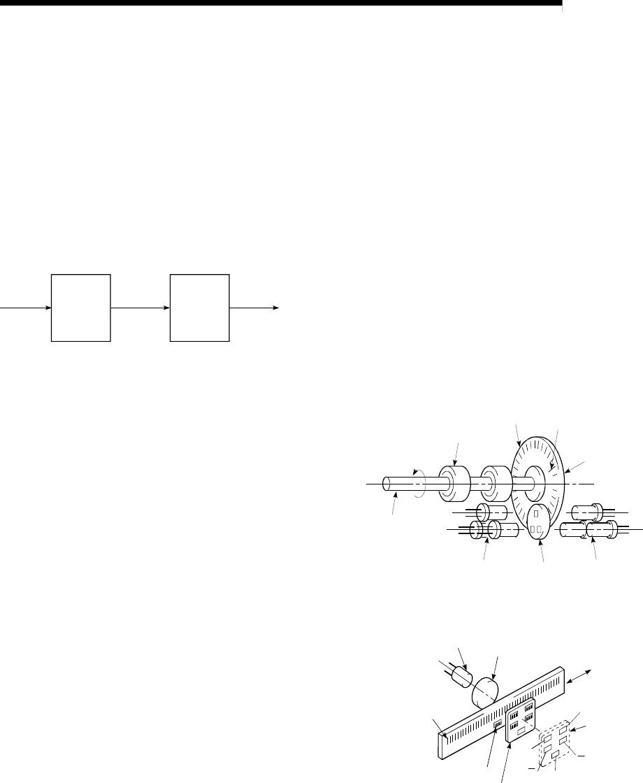
ENCODER
This device turns the input data into a binary
code of 1 (ON) and 0 (OFF). A type of pulse
generator.
A
B
Z
Ball bearing
For the main
signal
For the zero
point signal
Input axis
Code disk
Photoreceptor
(phototransistor)
Index
scale
Light source
(light-emitting diode)
Rotary encoder
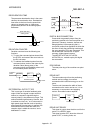
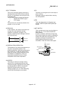
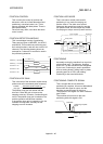
a
a
b
z
b
Light source
(LED)
Collimator lens
Main scale
Photorecepto
r
(photodiode)
Reference
zero point
Index
scale
Linear encoder