3 - 11
MELSEC-
A
3 SPECIFICATIONS AND FUNCTIONS
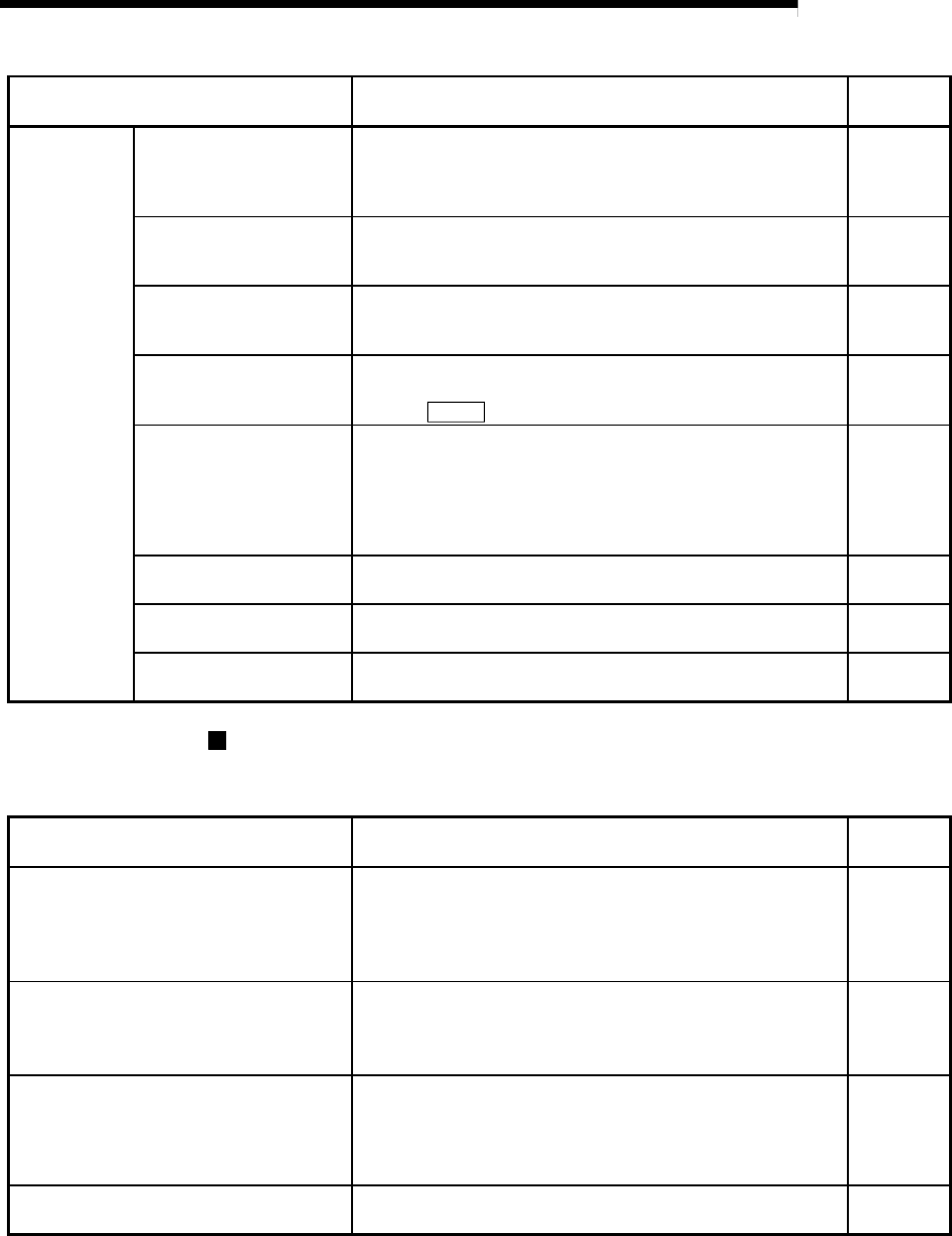
Auxiliary function Details
Reference
section
Other functions
Step function
This function temporarily stops the operation to confirm the
positioning operation during debugging, etc.
The operation can be stopped at each "automatic deceleration"
or "positioning data".
12.7.1
Skip function
This function stops (decelerates to a stop) the positioning being
executed when the skip signal is input, and carries out the next
positioning.
12.7.2
M code output function
This function issues an auxiliary work (clamp or drill stop, tool
change, etc.) according to the code No. (0 to 32767) set for
each positioning data.
12.7.3
Teaching function
This function stores the address positioned with manual control
into the positioning address having the designated positioning
data No (
Cd.5
).
12.7.4
Command in-position
function
At each automatic deceleration, this function calculates the
remaining distance for the D75P2 to reach the positioning stop
position, and when the value is less than the set value, turns
ON the "command in-position signal".
When using another auxiliary work before ending the control,
use this function as a trigger for the auxiliary work.
12.7.5
Stepping motor mode
function
This function makes settings for using a stepping motor. 12.7.6
Acceleration/deceleration
process function
This function adjusts the control acceleration/deceleration. 12.7.7
Indirectly specification
function
This function specifies indirectly and starts the positioning data
No.
12.7.8
Common functions
The outline of the functions executed as necessary are described below.
(Refer to "SECTION 2" for details on each function.)
Common functions Details
Reference
section
Parameter initialization function
This function returns the "setting data" stored in the D75P2
flash ROM to the default values.
The following two methods can be used.
1) Method using sequence program
2) Method using AD75 software package
13.2
Execution data backup function
This functions stores the "setting data", currently being
executed, into the flash ROM.
1) Method using sequence program
2) Method using AD75 software package
13.3
LED display function
This function displays the D75P2 operation state, signal state
and error details on the 17-segment LED on the front of the
main module.
The display details can be changed with the mode switch on
the front of the main module.
13.4
Clock data function
This function sets the PLC CPU clock data in the D75P2. This
used for the various history data.
13.5


