Appendix - 25
MELSEC-
A
APPENDICES
Appendix 10 Comparisons with A1SD75P -S3 and AD75P -S3 modules
(1) The following functions have been added.
• Data setting method zero point return .............. Refer to section 8.3
• Speed/position changeover control function (ABS mode)
............................................................................ Refer to section 9.2.9
• Absolute position detection function ................. Refer to section 12.6
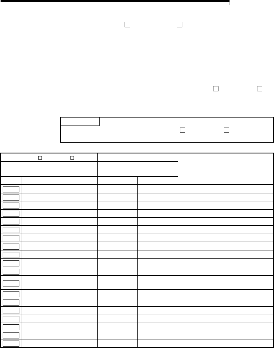
(2) The following buffer memory addresses of the A1SD75P
-S3 and AD75P -S3
correspond to the remote input/output and remote registers of the D75P2.
POINT
The buffer memory addresses of the A1SD75P -S3 and AD75P -S3 indicated in
the following table are disallowed for use in the D75P2.
A1SD75P -S3, AD75P -S3
AJ65BT-D75P2-S3
Name
Buffer memory addresses
Remote input/output,
remote register
Symbol Axis 1 Axis 2 Axis 1 Axis 2
Cd.11
1150 1200 RWwm RWwm+8
Positioning start No.
Cd.12
1151 1201 RY(n+2)4 RY(n+4)4 Axis error reset
Cd.13
1152 1202 RY(n+2)5 RY(n+4)5
Restart command
Cd.14
1153 1203 RY(n+2)6 RY(n+4)6
M code OFF request
Cd.15
1154, 1155 1204, 1205 RWwm+2 to 3 RWwm+10 to 11
New current value
Cd.16
1156, 1157 1206, 1207 RWwm+4 to 5 RWwm+12 to 13 New speed value
Cd.17
1158 1208 RY(n+2)7 RY(n+4)7
Speed change request
Cd.18
1159 1209 RWwm+1 RWwm+9
Positioning operation speed override
Cd.19
1160, 1161 1210, 1211 RWwm+6 to 7 RWwm+14 to 15
JOG speed
Cd.20
1163 1213 RY(n+2)8 RY(n+4)8
Speed/position changeover enable flag
Cd.22
1167 1217 RY(n+2)9 RY(n+4)9
Manual pulse generator enable flag
Cd.24
1170 1220 RY(n+2)A RY(n+4)A
Zero point return request flag OFF
request
Cd.25
1171 1221 RY(n+2)B RY(n+4)B
External start valid
Md.29
800, 801 900, 901 RWrn+0 to 1 RWrn+8 to 9
Current feed value
Md.31
804, 805 904, 905 RWrn+2 to 3 RWrn+10 to 11
Feedrate
Md.32
806 906 RWrn+4 RWrn+12
Valid M code
Md.33
807 907 RWrn+5 RWrn+13
Axis error No.
Md.34
808 908 RWrn+6 RWrn+14 Axis warning No.
Md.35
809 909 RWrn+7 RWrn+15 Axis operation status


