


Appendix - 41
MELSEC-
A
APPENDICES
POSITIONING DATA
This is data for the user to carry out
positioning. The No. of points to which
positioning is carried out (the No. of
addresses) is designated by the user. In the
D75P2, this is a maximum of 600 points.
As a principle, positioning is executed in the
order of the data Nos.
POSITIONING PARAMETER
This is basic data for carrying out positioning
control. Types of data include control unit,
movement amount per pulse, speed limit
value, upper and lower stroke limit values,
acceleration/deceleration time, positioning
method, etc.
Parameters have an initial value, so that value
is changed to match the control conditions.
POSITIONING START
This refers the act of designating a target data
No. and starting the positioning.
The operation after the positioning is complete
for that data No. is determined by the data
No.'s positioning pattern.
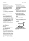
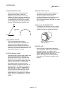
PTP Control (Point To Point Control)
This is a type of positioning control. With this
control method, the points to be passed are
designated at random locations on the path.
Movement only to a given target positioning is
requested. Path control is not required during
movement from a given point to the next value.
PU (Programming Unit)
This is the abbreviation for "programming unit".
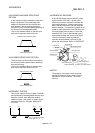
PULSE
The turning ON and OFF of the current
(voltage) for short periods. A pulse train is a
series of pulses. The D75P2 is the module that
generates the pulses.
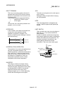
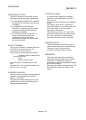
PULSE GENERATOR
This is a device that generates pulses.
Examples include devices installed on the
motor shaft that create pulses when the shaft
rotates, and digital devices.
1-phase types output one pulse train. 2-phase
types output two pulse trains with a phase
difference. From 600 to 1,000,000 pulses can
be output per shaft rotation. Generators with a
ZERO POINT signal function to output 1 or 2
pulses per shaft rotation. Abbreviated as PLG.
Refer to the term "ENCODER".
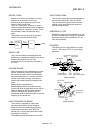
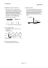
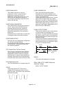
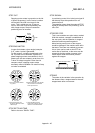
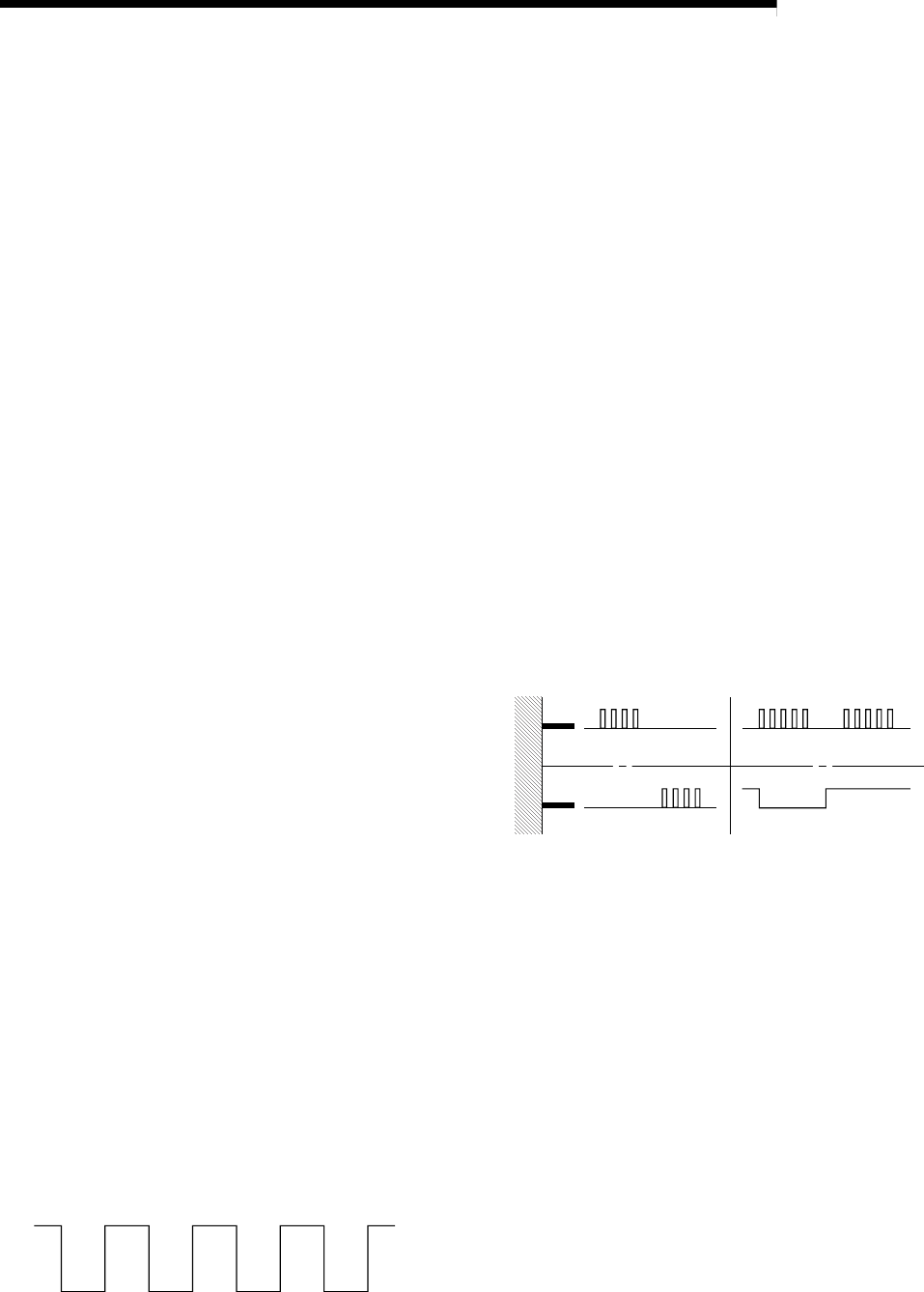
PULSE OUTPUT MODE
There are two methods used to issue forward
run and reverse run commands to the
servomotor. The type used differs according to
the machine maker. In type A, the forward run
pulses and reverse run pulses are output from
separate terminals.
In type B, the forward run pulses and reverse
run pulses are output from the same terminal,
and a forward/reverse run identification signal
is output from another terminal.
Forward
Reverse
Terminal
A type B type
Reverse
Forward
READY
This means that preparation is complete.
REAL-TIME AUTO TUNING (Real-time
Automatic Tuning)
Refer to "AUTO TUNING".