


4 - 7
MELSEC-
A
4 INSTALLATION, WIRING AND MAINTENANCE OF THE PRODUCT
4.2 Installation
4.2.1 Precautions for installation
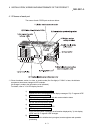
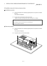
This section explains the installation of the D75P2.
The D75P2 is installed in either of the following two methods.
• Installed on DIN rail
• Installed on control box
Refer to this section as well as section "4.1.3 Handling precautions" when carrying out
the work.
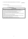
(1) Precautions for installation
!
CAUTION
Use the PLC within the general specifications environment given in this manual.
Using the PLC outside the general specification range environment could lead to electric
shocks, fires, malfunctioning, product damage or deterioration.
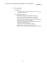
Tighten the module mounting screws to the specified torque.
Undertightening can cause a short circuit, fire or malfunction.
Overtightening can cause a drop, short circuit or malfunction due to damaged screws or
module.
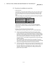
Screw location Tightening torque range
Module mounting screw (M4 screw) 0.78 to 1.18N•m
Do not touch the conductors and electronic parts of the module directly.
Doing so can cause a malfunction or failure.
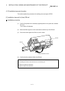
Fit the external device connection connector and peripheral device connection connector
securely into the connectors of the module, and confirm that they click.
Incorrect fitting can result in poor contact, causing false input or false output.
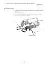
When the drive unit and peripheral device are not connected, always mount the connector
covers. Failure to do so can cause a malfunction.