


5 - 76
MELSEC-
A
5 DATA USED FOR POSITIONING CONTROL
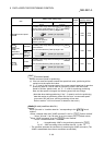
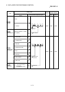
5.5 List of condition data
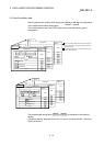
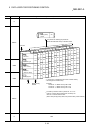
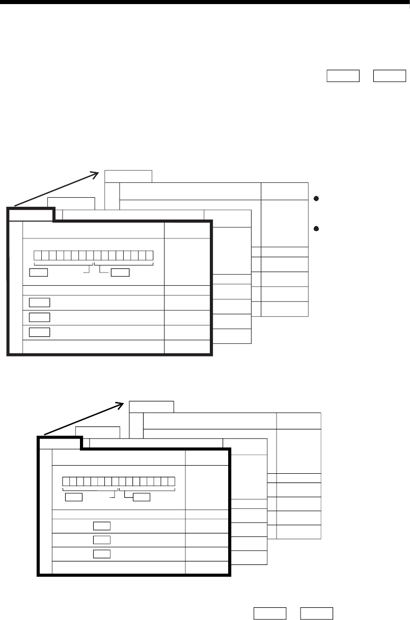
Before explaining the condition data setting items Da.14 to Da.18 , the configuration
of the condition data will be shown below.
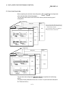
The condition data stored in the D75P2 buffer memory has the following type of
configuration.
No.10
Setting item
4490
4491
4492
4493
4494
4495
4496
4497
4498
4499
No.2
Setting item
4410
4411
4412
4413
4414
4415
4416
4417
4418
4419
Buffer memory
address
Buffer memory
address
No.1
Setting item
4400
Da.16 Address
Open
Open
Da.17
Da.18
b15 b0
b7
b8b11b12
Condition operator
Da.14
Condition target
4401
4402
4403
4404
4405
4406
4407
4408
4409
Buffer memory
address
Da.15
Parameter 2
Parameter 1
Up to 10 condition data items can be set (stored)
for each block No. in the buffer memory address
shown on the left.
One condition data item is configured of the items
shown in the bold box.
4740
4741
4742
4743
4744
4745
4746
4747
4748
4749
4660
4661
4662
4663
4664
4665
4666
4667
4668
4669
4650
b15 b0b7b8b11b12
4651
4652
4653
4654
4655
4656
4657
4658
4659
Open
Setting item
Buffer memory
address
Setting item
Buffer memory
ddress
Setting item
Buffer memory
address
Open
AddressDa.16
Da.15
Condition operator
Da.14
Condition target
Parameter 1Da.17
Parameter 2Da.18
Axis 2
No.1
No.2
No.10
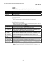
The condition data setting items (
Da.14 to Da.18 ) are explained in the following
section.
(The buffer memory addresses for the axis 1 to axis 2 "condition data No. 1 (block No.
7000)" are shown.)