


1 - 20
MELSEC-
A
1 PRODUCT OUTLINE
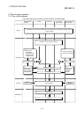
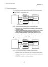
1.3.2 Transient transmission
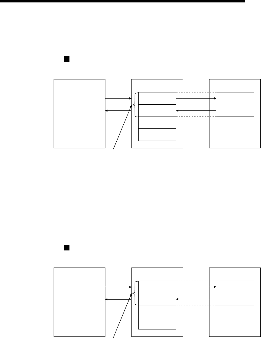
This section explains transient transmission between the D75P2 and master module.
When FROM/TO commands are used
PLC CPU Master module
D75P2 (Station No. 1)
Buffer memory
(Transmission/reception
area)
Transmission area
Reception area
Transmission/
reception area for
station No. 2
:
Buffer memory
2)
3)
1)
4)
Transmission/reception area of station No. 1
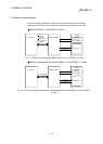
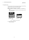
Fig. 1.8 Transient transmission (When FROM/TO commands are used)
1) Data (control data + transmission data) are stored into the transmission area
of the master module.
2) When the intelligent device station access request signal (RY(n+7)E) is turned
ON, the data stored in the transmission area are stored into the D75P2.
3) When the intelligent device station access complete signal (RX(n+7)E) is
turned ON, a response is stored into the reception area of the master module.
4) Data are read from the reception area of the master module.
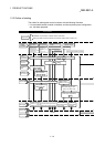
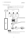
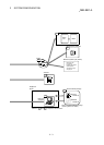
When dedicated commands (RIRD, RIWT) are used
PLC CPU Master module
D75P2 (Station No. 1)
:
Transient
transmission
Buffer memory
(Transmission/reception
area)
Transmission area
Reception area
Transmission/
reception area for
station No. 2
Buffer memory
1)
2)
Transmission/reception area of station No. 1
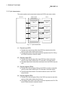
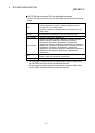
Fig. 1.9 Transient transmission (When dedicated commands are used)
1) When data (control data + transmission data) are stored into the word device
and the dedicated command is executed, the transmission data are stored into
the D75P2.
2) A response is stored into the specified word device.