


4 - 27
MELSEC-
A
4 INSTALLATION, WIRING AND MAINTENANCE OF THE PRODUCT
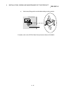
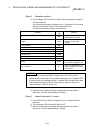
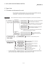
(Step 3) Operation monitor 2
1) The axis display LED for each axis will turn ON sequentially at an approx.
0.5 second interval.
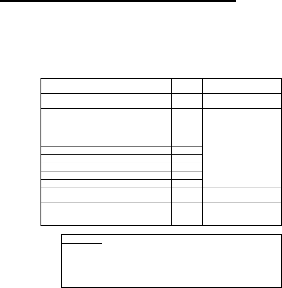
One of the following states will appear on the 17-segment LED to indicate
the state of the axis for which the axis display LED is ON.
Confirm that the display matches each axis state.
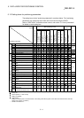
Axis state
17-segment
LED
Remarks
Idle IDLE
State when power is turned
ON/operation has ended.
Stopped STOP
State when positioning
operation is temporarily
stopped.
In JOG operation JOG
–
In manual pulse generator operation MANP
In zero point return OPR
In position control POSI
In speed control VELO
In speed control for speed/position changeover control V- P
In position control for speed/position changeover control V -P
Waiting BUSY
The execution is waiting due to
the condition designation, etc.
Error occurrence * E***
The error code appears in ***.
Refer to Chapter 14 for details
on the errors.
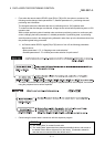
POINT
* When the Remote station READY signal (RX(n+7)B) is ON, even if a
parameter error occurs, the error code will not appear on the 17-segment LED.
If the error code is not displayed on the 17-segment LED, check the error code
with the peripheral device or D75P2 "Axis error No. (RWrn+5, RWrn+13)",
"Axis warning No. (RWrn+6, RWrn+14)".
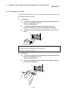
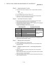
2) When the mode switch is pressed, the state will shift to the internal
information 1 monitor state described in (Step 4).
(Step 4) Internal information 1 monitor
1) The D75P2 OS type ("S003") will appear on the 17-segment LED for
reference.
2) The axis display LED for each axis will turn OFF.
3) When the mode switch is pressed, the state will shift to the internal
information 2 monitor state described in (Step 5).