11 - 18
MELSEC-
A
11 MANUAL CONTROL
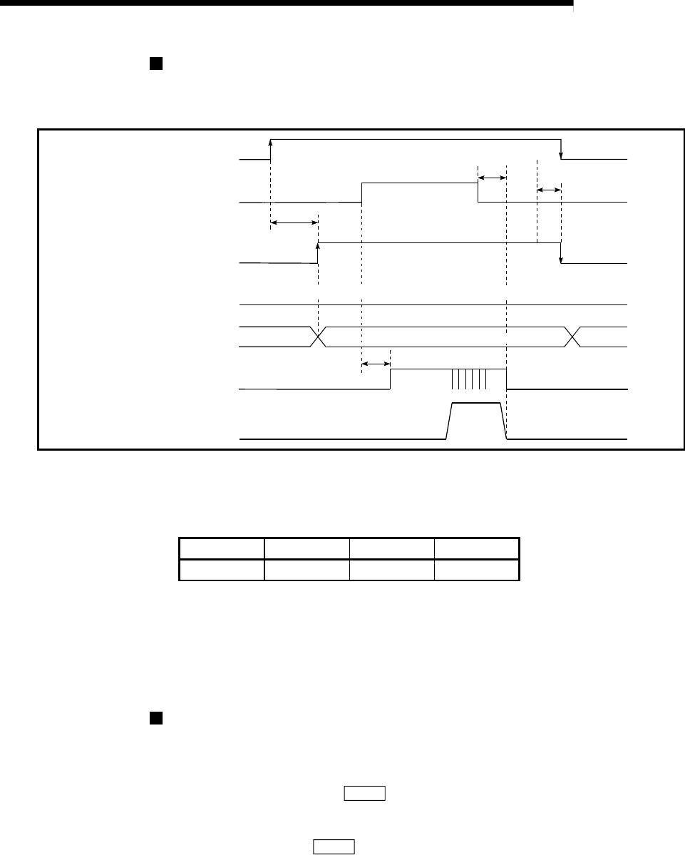
Manual pulse generator operation timing and processing time
The following drawing shows details of the manual pulse generator operation
timing and processing time.
Manual pulse generator input
pulses
t1
t3
t4
BUSY signal [RXn4, RXn5]
Standing by
Positioning start complete
signal [RXn1, RXn2]
Pulse output to an external
source (PULSE)
Positioning operation
t2
The start complete signal does not turn ON in manual pulse generator operation.
Manual pulse generator enable
flag [RY(n+2)9, RY(n+4)9]
Axis operation status
Standing by In manual pulse generator operation
[RWrn+7, RWrn+15]
Fig. 11.12 Manual pulse generator operation timing and processing times
Normal timing times Unit : [ms]
t1 t2 t3 t4
1 to 60 0 to 60 120 to 180 1 to 60
Delays may occur in the t1 timing time due to the following factors.
1) The operation status of other axes.
2) Whether there is intervention from a peripheral device during processing
the start process.
3) Details of the positioning data to be started.
Position control by manual pulse generator operation
The command output during manual pulse generator operation is as follows.
[No. of command pulses] = [No. of manual pulse generator input pulse]
[
Cd.23
Manual pulse generator 1 pulse input magnification]
[Command speed*] = [Manual pulse generator input frequency]
[
Cd.23
Manual pulse generator 1 pulse input magnification]
*: When the manual pulse generator input frequency changes, the new frequency
will apply after a maximum of 180ms delay.


