


8 - 14
MELSEC-
A
8 ZERO POINT RETURN CONTROL
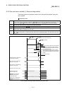
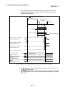
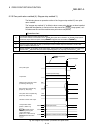
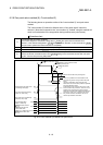
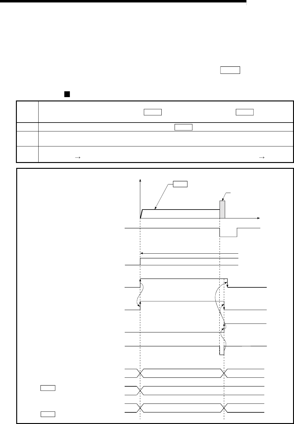
8.2.6 Zero point return method (4): Stopper stop method 3)
The following shows an operation outline of the "stopper stop method 3)" zero point
return method.
The "stopper stop method 3)" is effective when a near-point dog has not been installed.
(Note that the operation is carried out from the start at the "
Pr.49 Creep speed", so it
will take some time until the machine zero point return completion.)
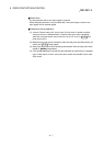
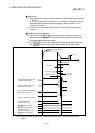
Operation chart
1)
The machine starts a machine zero point return.
(The machine moves in the direction set in "
Pr.46
Zero point return direction" at " Pr.49
Creep speed".
At this time, torque limit is required. If torque limit is not applied, the servomotor may fail at 2).)
2)
The machine comes into contact with the stopper at the "
Pr.49 Creep speed", and stops.
3)
At the zero point signal after the stop, pulse output from the D75P2 stops and "deviation counter clear
output" is output to the drive unit.
4)
After the completion of "deviation counter clear output", the zero point return complete flag (RX(n+2)0, RX(n+5)0)
turns from OFF ON and the zero point return request flag (RX(n+1)F, RX(n+4)F) turns from ON OFF.
t
ON
OFF
ON
OFF
OFF
ON
V
0
Pr. 49 Creep speed
Valid torque limit range
Machine zero point return start
(Positioning start signal)
Deviation counter clear output
Axis operation status
[RWrn+7, RWrn+15]
Standing by
Inconsistent Value the machine moved is stored
Zero point return request flag
[RX(n+1)F, RX(n+4)F]
Zero point return complete flag
[RX(n+2)0, RX(n+5)0]
Md.44 Movement amount
after near-point dog ON
Current feed value
[RWrn+0 to 1, RWrn+8 to 9]
Md.30 Machine feed value
Zero point address
In zero point return
Standing by
Inconsistent
Zero point signal
Torque limit
Stops at stopper
Fig. 8.9 Stopper stop method 3) machine zero point return