


5 - 43
MELSEC-
A
5 DATA USED FOR POSITIONING CONTROL
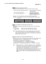
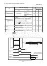
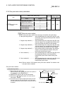
[Table 1]
Pr.11
setting value
Pr.1
setting value
Value set with peripheral device
(unit)
Value set with sequence program
(unit)
0 : Standard mode
0 : mm
0 to 10000.0 (
m)
0 to 100000 (
10
-1
m)
1 : inch 0 to 1.00000 (inch)
0 to 100000 (
10
-5
inch)
2 : degree 0 to 1.00000 (degree)
0 to 100000 (
10
-5
degree)
3 : pulse 0 to 100000 (pulse) 0 to 100000 (pulse)
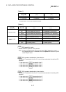
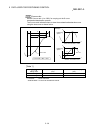
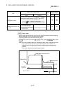
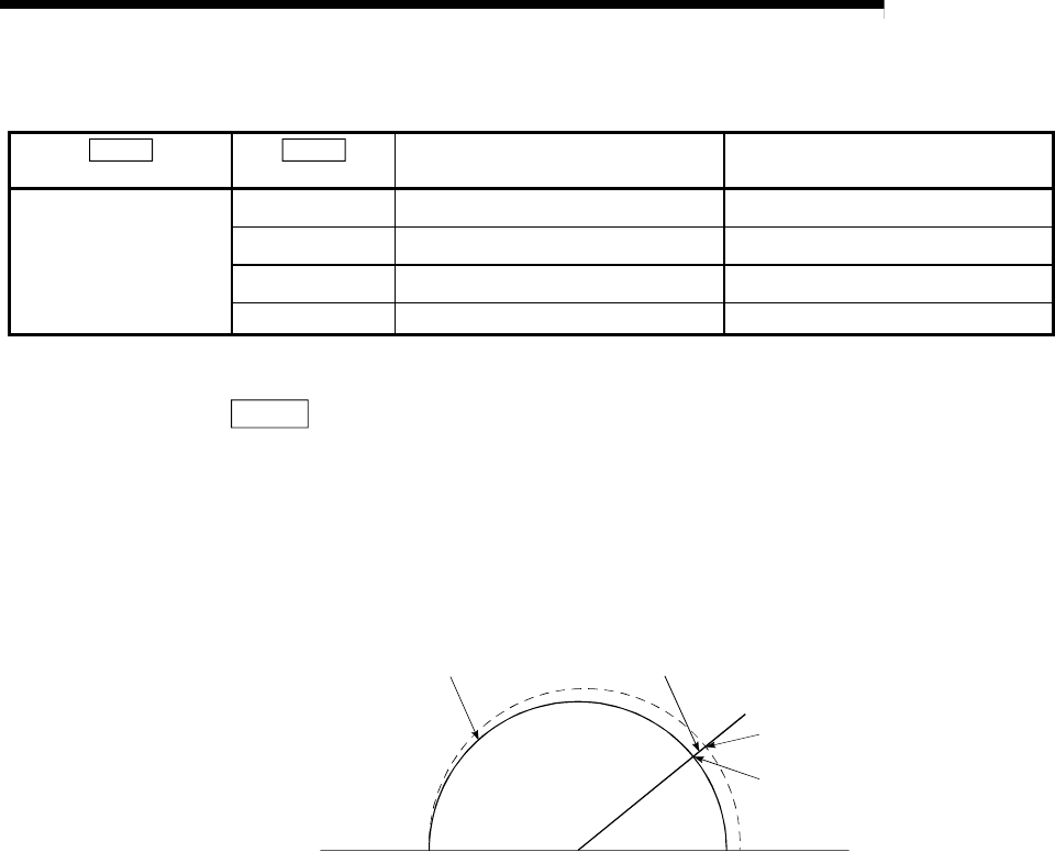
Pr.42
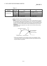
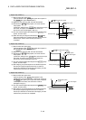
Allowable circular interpolation error width
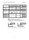
With the "allowable circular interpolation error width", the allowable error range of
the calculated arc path and end point address is set. If the error of the calculated
arc path and end point address is within the set range, circular interpolation will be
carried out to the set end point address while compensating the error with spiral
interpolation.
The allowable circular interpolation error width is set in the axis1 buffer memory
addresses [60, 61].
Path with spiral interpolation
Error
End point address
with calculation
End point address
Start point address Center point address
* With circular interpolation control using the center point designation, the arc
path calculated with the start point address and center point address and the
end point address may deviate.