


11 - 4
MELSEC-
A
11 MANUAL CONTROL
11.2 JOG operation
11.2.1 Outline of JOG operation
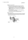
Important
Use the hardware stroke limit function when carrying out JOG operation near the
upper or lower limits. (Refer to section 12.4.4).
* If the hardware stroke limit function is not used, the workpiece may exceed the
operating range, causing an accident.
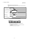
JOG operation
In JOG operation, the Forward run JOG start signal [RY(n+1)6, RY(n+1)8] or
Reverse run JOG start signal [RY(n+1)7, RY(n+1)9] turns ON, causing pulses to
be output to the drive unit from the D75P2 while the signal is ON. The workpiece is
then moved in the designated direction.
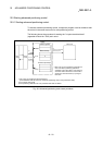
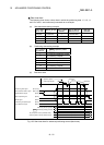
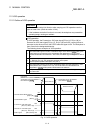
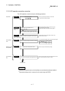
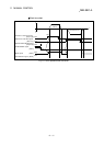
The following shows examples of JOG operation.
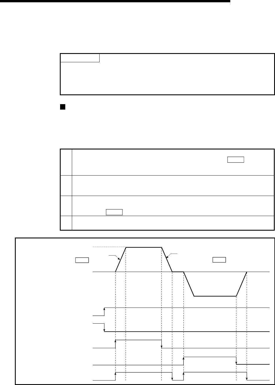
1)
When the START signal turns ON, acceleration begins in the direction designated by the
START signal, and continues for the acceleration time designated in "
Pr.33 JOG
operation acceleration time selection". At this time, the BUSY signal changes from OFF to
ON.
2)
When the workpiece being accelerated reaches the speed set in "JOG speed (RWwm+6
to 7, RWwm+14 to 15)", the movement continues at this speed.
Constant speed operation takes place at 2) and 3).
3)
When the START signal is turned OFF, deceleration begins from the speed set in "JOG
speed (RWwm+6 to 7, RWwm+14 to 15)", and continues for the deceleration time
designated in "
Pr.34 JOG operation deceleration time selection".
4)
The operation stops when the speed becomes 0. At this time, the BUSY signal changes
from ON to OFF.
Remote station READY signal
OFF
ON
Reverse run JOG start signal
OFF
ON
OFF
ON
BUSY signal
OFF
ON
Forward JOG run
Reverse JOG run
ON
OFF
D75P2 READY signal
Forward run JOG start signal
JOG speed
(RWwm+6 to 7, RWwm+14 to 15)
Acceleration for the acceleration
time selected in Pr. 33
Deceleration for the deceleration
time selected in Pr. 34
1) 2) 3) 4)
[RX(n+7)B]
[RXn0]
[RY(n+1)6, RY(n+1)8]
[RY(n+1)7, RY(n+1)9]
[RXn4, RXn5]
Fig. 11.3 JOG operation