


12 - 26
MELSEC-
A
12 CONTROL AUXILIARY FUNCTIONS
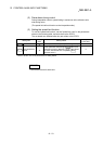
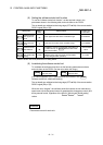
(4) Setting the torque limit function
(a) To use the "torque limit function", set the "torque limit value" in the
parameters shown in the following table, and write them to the D75P2.
The set details are validated at the rising edge (OFF
ON) of the remote
station READY signal [RX(n+7)B].
Setting item
Setting
value
Setting details
Factory-set
initial value
Pr.18
Torque limit
setting value
Set the torque limit value as a percentage. 300
Pr.56
Zero point return
torque limit value
Set the torque limit value to be used after starting the
deceleration to the "
Pr.49 Creep speed" with %.
300
* Refer to section "5.2 List of parameters" for setting details.
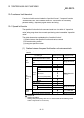
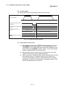
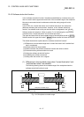
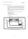
(b) The "torque limit value" set in the D75P2 is set in the "
Md.45 Torque limit
stored value". The "
Md.45 Torque limit stored value" in the sequence
program is transferred to the "D/A converter module", and the torque is
limited.
PLC CPU
Buffer memory
Drive unit
Writing by a
TO command
Stored torque
limit value
826
D/A convertor module
Reading by a
FROM command
(dedicated
command)
D75P2
Torque limiting
Positioning control
Fig. 12.14 Limiting the torque to the drive unit
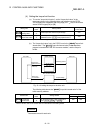
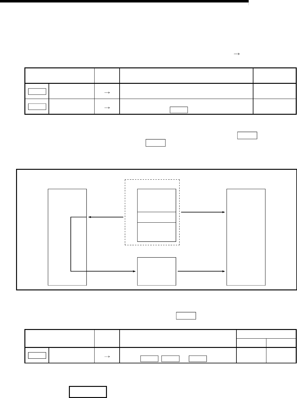
The following table shows the "
Md.45 Torque limit stored value" of the
buffer memory address.
Monitor item
Monitor
value
Storage details
Buffer memory address
Axis 1 Axis 2
Md.45
Torque limit
stored value
The "torque limit value" valid at that time is
stored. (
Pr.18 , Pr.56 , or
Cd.30
)
826 926
* Refer to section "5.6 List of monitor data" for information on the setting details.
REMARK
Parameters are set for each axis.