


6 - 21
MELSEC-
A
6 SEQUENCE PROGRAM USED FOR POSITIONING CONTROL
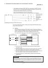
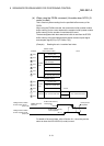
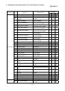
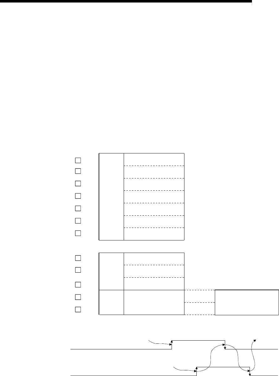
(d) When using the FROM command (Unusable when QCPU (Q
mode) is used)
This is used only when reading from the specified buffer memory of the
D75P2.
When using the FROM command, the transmission buffer (master module
buffer memory) for the control data and the reception buffer (master module
buffer memory) for the number of read data will be used.
The data designated with the transmission buffer is read from the D75P2
buffer memory using the intelligent device station access request signal
and complete signal (RY(n+7)E, RXS(n+7)E)).
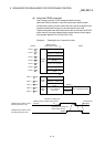
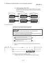
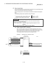
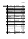
(Example) Reading the axis 1 machine feed value
D75P2
Intelligent device station
access request signal
(RY(n+7)E)
FROM command
execution
Intelligent device station
access complete signal
(RX(n+7)E)
1006
H
M
1005
H
M
1004
H
M
1003
H
M
1002
H
M
1001
H
M
1000
H
M
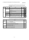
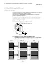
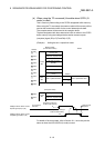
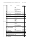
Address
Master module
(Transmission buffer)
Control
data
Dummy area
Station No., request code
Transmission buffer write
data size (byte)
Quantity
Access code, attribute
Buffer memory address
No. of write points (word)
802(322
H
)
803(323
H
)
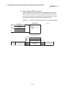
Address
1203
H
M
1204
H
M
(Reception buffer)
Complete status
1200
H
M
1201
H
M
1202
H
M
Read data
Station No., request code
No. of read data (byte)
Axis 1 machine feed value
Axis 1 machine feed value
D75P2 buffer memory
read request
Read process
completion
D75P2 buffer memory
read completion
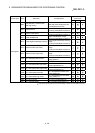
Control
data
For details of the control data, refer to Section 6.1.1 since they are the
same as when the ACPU/QCPU (A mode) is used.