


3 - 19
MELSEC-
A
3 SPECIFICATIONS AND FUNCTIONS
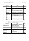
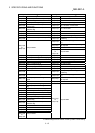
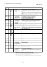
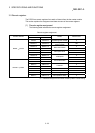
Device
No.
Signal name Details
RX(n+1)E
RX(n+4)E
Axis 1
Axis 2
Command
in-position
signal
OFF: Outside in-position
range
ON: Within in-position
range
This signal turns ON when the remaining distance falls within the
"command in-position range" set in the parameter.
This signal turns OFF when the axis of the corresponding operation
moves.
A command in-position check is performed every 56.8ms during position
control.
During speed control or during speed control of speed/position changeover
control, a command in-position check is not performed. (*
1
)
RX(n+1)F
RX(n+4)F
Axis 1
Axis 2
Zero point
return
request flag
OFF: Machine zero point
return complete
ON: Machine zero point
return being
requested
This flag turns ON when any of the following conditions occurs, and turns
OFF at completion of a machine zero point return. (*
1
)
(a) When the drive unit READY signal turns OFF
(b) When the remote station READY signal turns ON
(c) When a machine zero point return starts
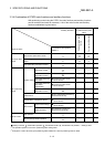
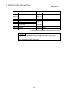
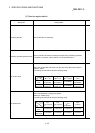
RX(n+2)0
RX(n+5)0
Axis 1
Axis 2
Zero point
return
complete
flag
OFF: Before machine
zero point return
completion
ON: After machine zero
point return
completion
This flag turns ON at normal completion of a machine zero point return.
This flag turns OFF at a machine zero point return start, positioning
operation start, JOG operation start or manual pulse generator operation
start or when the drive unit READY signal turns OFF. (*
1
)
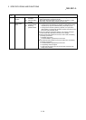
RX(n+2)1
RX(n+5)1
Axis 1
Axis 2
Warning
detection
OFF: Without axis warning
ON: With axis warning
This signal turns ON when an axis warning occurs.
This signal turns OFF when the axis error is reset. (*1)
RX(n+2)2
RX(n+5)2
Axis 1
Axis 2
Speed
change 0
flag
OFF: New speed value is
other than 0
ON: New speed value is
0
This signal turns ON when Speed change request (RY(n+2)7, RY(n+4)7)
is turned ON at a new speed value of 0.
This signal turns OFF when Speed change request is turned ON at a new
speed value of other than 0. (*
1
)
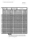
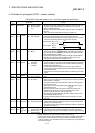
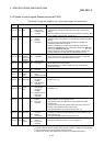
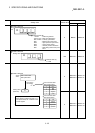
RX(n+2)3
RX(n+5)3
Axis 1
Axis 2
Zero point
absolute
position
overflow flag
OFF: Overflow not
occurred
ON: Overflow occurred
This signal turns ON when the zero point absolute position (*
2
) has
overflown due to a current value change. (*
1
)
RX(n+2)4
RX(n+5)4
Axis 1
Axis 2
Zero point
absolute
position
underflow
flag
OFF: Underflow not
occurred
ON: Underflow occurred
This signal turns ON when the zero point absolute position (*
2
) has
underflown due to a current value change. (*
1
)
RX(n+2)5
RX(n+5)5
Axis 1
Axis 2
ABS data bit
0
OFF: bitOFF
ON: bitON
This signal indicates the low-order bit of ABS data. (*
3
)
RX(n+2)6
RX(n+5)6
Axis 1
Axis 2
ABS data bit
1
OFF: bitOFF
ON: bitON
This signal indicates the high-order bit of ABS data. (*
3
)
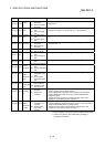
RX(n+2)7
RX(n+5)7
Axis 1
Axis 2
Transmissio
n data
READY flag
OFF: Trans-mission data
being prepared
ON: Trans-mission data
ready
This signal indicates the preparation condition of transmission data in the
ABS transfer mode. (*
3
)
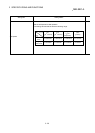
RX(n+2)8
RX(n+5)8
Axis 1
Axis 2
Restart
acceptance
complete flag
OFF: Restart not accepted
ON: Restart accepted
This signal indicates a restart acceptance condition.
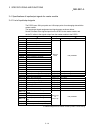
Initial data processing request
RX(n+7)8 Initial data
processing request
OFF: No initial data
processing request
ON: Initial data
processing being
requested
After power-on or after a hardware reset, the D75P2 turns ON Initial data
request to request initial data setting.
This signal turns OFF when Initial data processing complete (RY(n+7)8)
turns ON.
n: Address assigned to the master module by station number setting
*
1
: Updated every 56.8ms. (Not update when processing is completed within 56.8ms.)
*
2
: Refer to section 12.6 for the zero point absolute position.
*
3
: Used for maintenance of the absolute position detection system. Unusable for normal operation.