


12 - 27
MELSEC-
A
12 CONTROL AUXILIARY FUNCTIONS
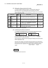
12.4.3 Software stroke limit function
In the "software stroke limit function" the address established by a machine zero point
return is used to set the upper and lower limits of the moveable range of the workpiece.
Movement commands issued to addresses outside that setting range will not be
executed.
In the D75P2, the "current feed value" and "machine feed value" are used as the
addresses indicating the current position. However, in the "software stroke limit
function", the address used to carry out the limit check is designated in the "
Pr.15
Software stroke limit selection". (Refer to section "9.1.4 Confirming the current value"
or details on the "current feed value" and "machine feed value".)
The upper and lower limits of the moveable range of the workpiece are set in "
Pr.13
Software stroke limit upper limit value"/ "
Pr.14 Software stroke limit lower limit value".
The details shown below explain about the "software stroke limit function".
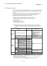
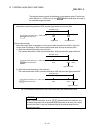
(1) Differences in the moveable range when "current feed value" and "machine feed
value" are selected.
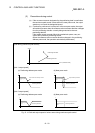
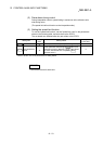
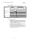
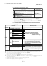
(2) Software stroke limit check details
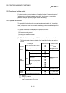
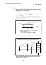
(3) Relation between the software stroke limit function and various controls
(4) Precautions during software stroke limit check
(5) Setting the software stroke limit function
(6) Invalidating the software stroke limit
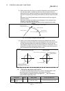
(7) Setting when the control unit is "degree"
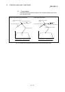
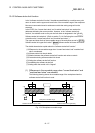
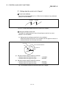
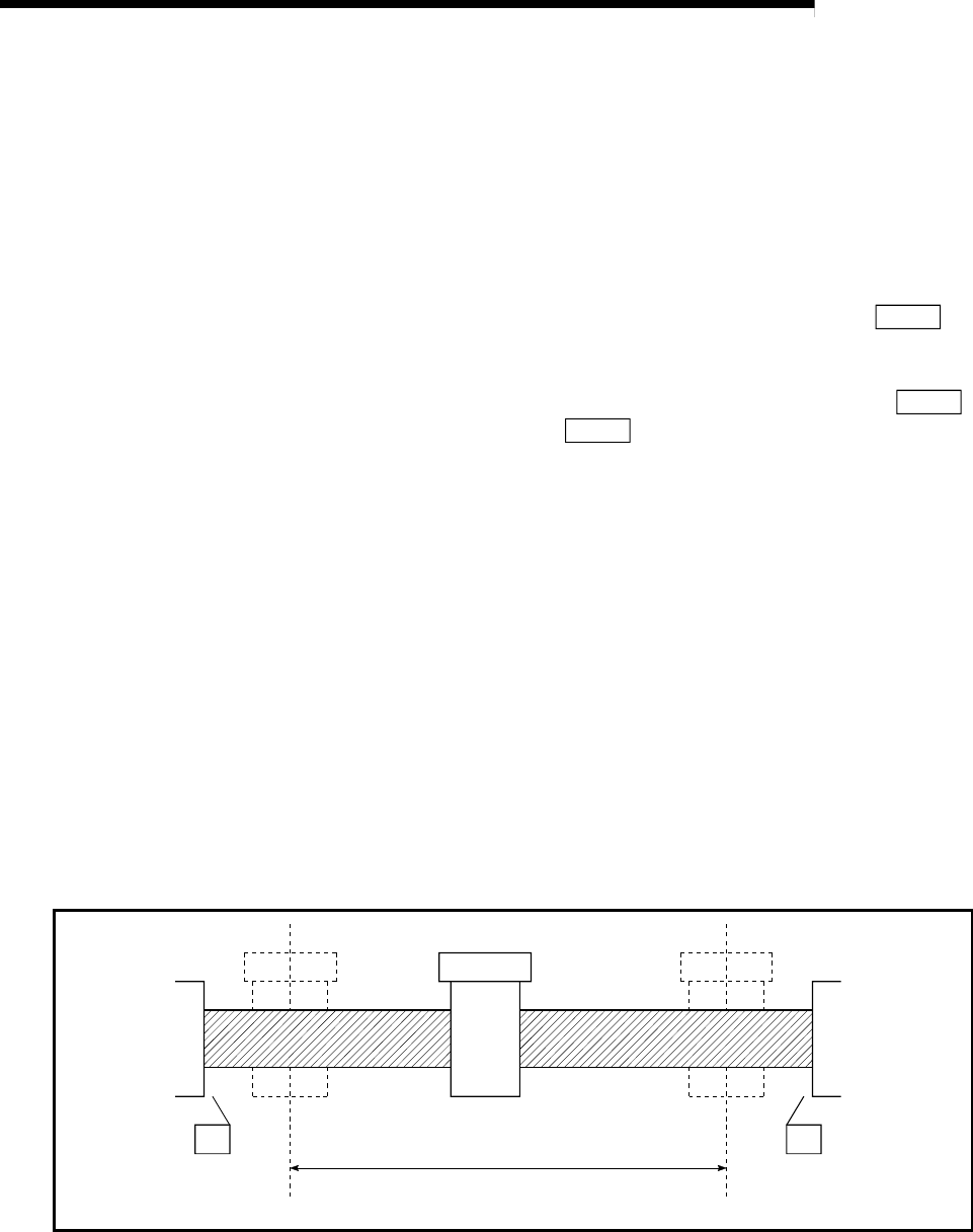
(1) Differences in the moveable range when "current feed value" and
"machine feed value" are selected.
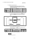
The following drawing shows the moveable range of the workpiece when the
software stroke limit function is used.
FLS
RLS
Workpiece moveable range
Software stroke limit
(
lower limit
)
Software stroke limit (upper limit)
Fig. 12.15 Workpiece moveable range