


3 - 21
MELSEC-
A
3 SPECIFICATIONS AND FUNCTIONS
3.4.3 Details of output signals (Master module D75P2)
The ON/OFF timing and conditions, etc., of the output signals are shown below.
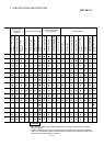
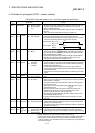
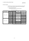
Device
No.
Signal name Details
RY(n+1)0
RY(n+1)1
Axis 1
Axis 2
Positioning
start
OFF : No positioning
start request
ON : Positioning start
requested
Zero point return or positioning operation is started.
The positioning start signal is valid at the rising edge, and carries out
starting.
When the positioning start signal turns ON during BUSY, the warning “start
during operation” (warning code: 100) will occur.
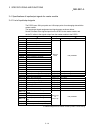
RY(n+1)3
RY(n+1)4
Axis 1
Axis 2
Axis stop OFF : No axis stop
request
ON : Axis stop
requested
When the axis stop signal turns ON, the zero point return control,
positioning control, JOG operation and manual pulse generator operation
will stop.
By turning the axis stop signal ON during positioning operation, the
positioning operation will be "stopped".
Whether to decelerate or suddenly stop for each stop group can be
selected with "
Pr.38
Stop group 1 sudden stop selection" to "
Pr.40
Stop group 3 sudden stop selection".
During interpolation control of the positioning operation, if the axis stop
signal for either axis turns ON, both axes will decelerate and stop.
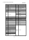
RY(n+1)6
RY(n+1)8
Axis 1
Axis 2
Forward run
JOG start
Reverse run
JOG start
OFF : JOG not started
ON : JOG started
When the Forward run JOG start signal is ON, Forward run JOG operation
will be carried out at the JOG speed. When the Forward run JOG start
signal turns OFF, the system will decelerate and stop.
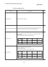
RY(n+1)7
RY(n+1)9
Axis 1
Axis 2
Reverse run
JOG start
OFF : JOG not started
ON : JOG started
When the Reverse run JOG start signal is ON, Reverse run JOG operation
will be carried out at the JOG speed.
When the Reverse run JOG start signal turns OFF, the system will
decelerate and stop.
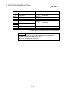
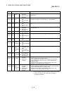
RY(n+2)0
RY(n+4)0
Axis 1
Axis 2
Servo ON
OFF : Servo OFF
ON : Servo ON
This signal turns ON when servo is to be switched ON. (*2)
RY(n+2)1
RY(n+4)1
Axis 1
Axis 2
ABS
transfer
mode
OFF : Non-ABS transfer
mode
ON : ABS transfer mode
This signal turns ON when the ABS transfer mode is to be selected. (*1)
RY(n+2)2
RY(n+4)2
Axis 1
Axis 2
ABS
request flag
OFF : ABS data request
acceptance
complete
ON : ABS data being
requested
This signal turns ON when ABS data is to be requested in the ABS
transfer mode. (*1)
RY(n+2)3
RY(n+4)3
Axis 1
Axis 2
Deviation
counter
clear
OFF : Deviation counter
clear request
acceptance
complete
ON : Deviation counter
clear being
requested
This signal turns ON when the deviation counter of the servo amplifier is to
be cleared. (*1)
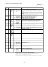
RY(n+2)4
RY(n+4)4
Axis 1
Axis 2
Error reset OFF : No error reset
request
ON : Error reset
requested
This signal is used to clear the axis error detection, axis error number, axis
warning detection and axis warning number.
This signal turns ON when ABS data is to be requested in the ABS
transfer mode.
This signal changes the axis operation status from error occurrence to
standby. (The signal does nothing during a start.)
This signal executes an error reset on its rising edge. (*3)
RY(n+2)5
RY(n+4)5
Axis 1
Axis 2
Restart
command
OFF : No restart
command
ON : Restart
commanded
Turning ON this signal when the axis operation status is a stop starts
positioning from the stop position to the end point of the positioning data
that caused the stop.
This signal executes a restart on its rising edge. (*3)
RY(n+2)6
RY(n+4)6
Axis 1
Axis 2
M code
OFF
request
OFF : No M code OFF
request
ON : M code OFF
requested
M code OFF request turns OFF the M code ON signal (RXnD, RXnE).
This signal executes M code OFF on its rising edge. (*3)
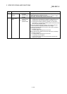
n: Address assigned to the master module by station number setting
*
1
: Used for maintenance of the absolute position detection system. Unusable for normal operation.
*
2
: Used for operation of the absolute position detection system.
*
3
: Updated every 56.8ms. (Not updated when processing is completed within 56.8ms.)