


14 - 11
MELSEC-
A
14 TROUBLESHOOTING
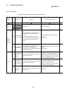
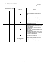
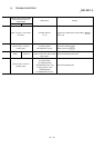
Relevant buffer memory address
remote input/output device, or
remote register
Setting range Remedy
Axis 1 Axis 2
Check the I/F on the PC side of cable connection for
errors.
After making an axis error reset (refer to [3] in Section
14.2), perform manual control operation (refer to Chapter
11) to move the axis to the position where the upper limit
signal (FLS) will not be turned OFF.
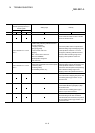
After making an axis error reset (refer to [3] in Section
14.2), perform manual control operation (refer to Chapter
11) to move the axis to the position where the lower limit
signal (RLS) will not be turned OFF.
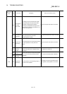
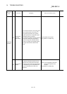
Check the ON/OFF statuses of the stop command (output
signal/external input issued to D75P2) and turn OFF the
active stop commands.
Output signals issued to D75P2 ... Axis 1: RY(n+1)3,
Axis 2: RY(n+1)4
External inputs ... External device connection connector:
Stop signal (STOP)
After checking the status of the stop command, perform
axis error resetting (refer to [3] in section 14.2) to remove
the error, then turn ON the start signal.
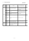
Turn ON the remote station READY signal (RX(n+7)B)
with the BUSY signals of all axes OFF.
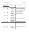
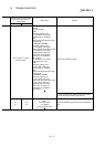
78 228
<Zero point return retry>
0, 1
The zero point return retry function (refer to section
12.2.1) is validated (setting: 1).
Using manual control operation (refer to Chapter 11) to
move from the current position (zero point) and perform
machine zero point return.