


12 - 38
MELSEC-
A
12 CONTROL AUXILIARY FUNCTIONS
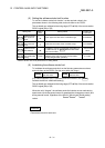
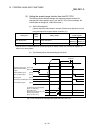
(3) Setting the speed change function from the PLC CPU
The following shows the data settings and sequence program example for
changing the control speed of axis 1 from the PLC CPU. (In this example, the
control speed is changed to "10000.00mm/min".)
(a) Set the following data.
(Use the start time chart shown in section (2) below as a reference, and set
using the sequence program shown in section (3).)
Setting item
Setting
value
Setting details
Remote input/output,
remote register
Axis 1 Axis 2
New speed value 1000000 Set the new speed.
RWwm+4
RWwm+5
RWwm+12
RWwm+13
Speed change request ON Set "ON: Change the speed". RY(n+2)7 RY(n+4)7
* Refer to section "3.4 Specifications of input/output signals for master module" and "3.5 Remote registers" for
details on the setting details.
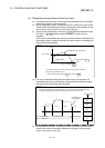
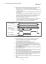
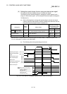
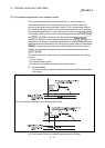
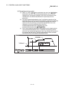
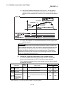
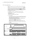
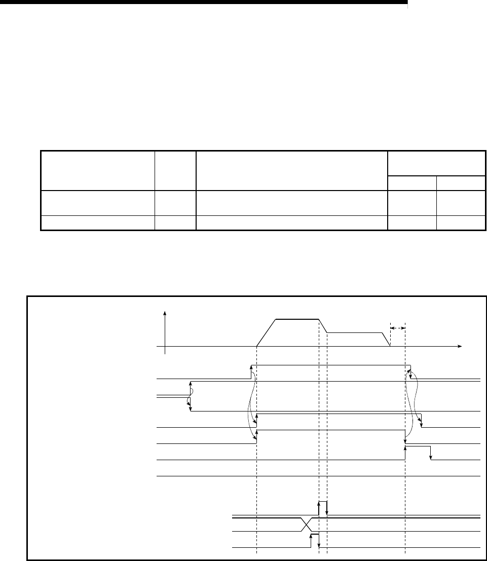
(b) The following shows the speed change time chart.
Speed change request
New speed value
In speed change processing flag
BUSY signal
D75P2 READY signal
Error detection signal
V
t
1000000
Start complete signal
Dwell time
Remote station READY
signal
Positioning start signal
Positioning complete signal
[RY(n+1)0]
[RX(n+7)B]
[RXn0]
[RXn1]
[RXn4]
[RXn7]
[RXnA]
[RX(n+1)1, RX(n+4)1]
[RWwm+4 to 5, RWwm+12 to 13]
[RY(n+2)7, RY(n+4)7]
Fig. 12.25 Time chart for changing the speed from the PLC CPU