


4 - 28
MELSEC-
A
4 INSTALLATION, WIRING AND MAINTENANCE OF THE PRODUCT
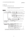
(Step 5) Internal information 2 monitor
1) The D75P2 OS version will appear on the 17-segment LED for reference.
Version
[V000]
2) The axis display LED for each axis will turn OFF.
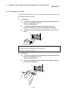
3) When the mode switch is pressed, the state will shift to the input/output
information n monitor state described in (Step 6).
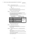
(Step 6) Input/output information n monitor
1) Each time the mode switch is pressed, the following input/output signal
names will sequentially appear on the 17-segment LED.
2) The signal state of each axis displayed on the 17-segment LED is displayed
with the axis display LED for each axis.
Confirm that the display matches each signal state.
When signal is ON .................... Axis display LED turns ON
When signal is OFF ................... Axis display LED turns OFF
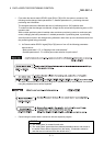
17-segment LED Target input/output signal name Remarks
SVON Drive unit READY signal
Changes sequentially
with each press of the
mode switch.
Z-ON Zero point signal
ULMT Upper limit signal
LLMT Lower limit signal
V-P Speed/position changeover signal
DOG Near-point dog signal
3) When the mode switch is pressed, the state will shift to the stepping motor
mode monitor state described in (Step 7).
(Step 7) Stepping motor mode monitor
1) "STMM" will appear on the 17-segment LED.
2) The axis display LED corresponding to the axis set to the stepping motor
mode will turn ON.
(Step 8) Shifting to operation monitor 1, and ending the operation
monitor
1) When the mode switch is pressed, the state will return to the operation
monitor 1 (Step 2).
Each time the mode switch is then pressed, the operation monitors between
(Step 2) and (Step 7) will be repeated.
2) To end the operation monitor, enter the monitor state between (Step 2) and
(Step 7) required by the user.