


13 - 9
MELSEC-
A
13 COMMON FUNCTIONS
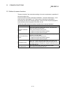
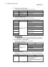
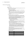
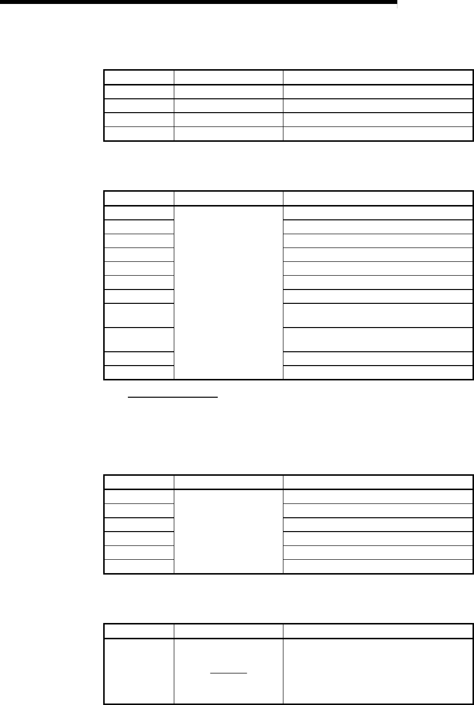
(1) "Module status" display details
"Module status" displays the operation status of the D75P2.
17-segment LED Axis indicator LED Details
RUN Operating axis flickers. During axis operation
TEST All axes turn on. During test mode
IDL Off During standby
ERR LED of axis in error flickers. During error occurrence
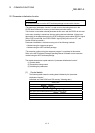
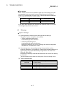
(2) Axis status" display details
"Axis status" displays the operation statuses of the axes.
The status of one axis is switched to that of the other every 0.5 seconds.
17-segment LED Axis indicator LED Details
IDLE
The lit LED changes every
0.5 seconds.
During standby
STOP During stop
JOG During JOG operation
MANP During manual pulse generator operation
OPR During zero point return
POSI During position control
VELO During speed control
V- P
During speed control of speed/position
changeover control
V -P
During position control of speed/position
changeover control
BUSY During condition waiting, etc.
E*** At error occurrence
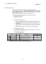
Error number display
When the axis has an error, the error number that has occurred in that axis
is displayed 0.5 seconds, and the status of the next axis is then displayed.
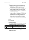
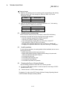
(3) "I/O information n" display details
"I/O information n" displays the status of each signal.
The "Axis indicator LED" turns on.
17-segment LED Axis indicator LED Details
SVON
Lit when the displayed
signal is ON.
Drive unit READY signal
Z-ON Zero point signal
ULMT Upper limit signal
LLMT Lower limit signal
V-P Speed/position changeover signal
DOG Near-point dog signal
(4) Other display details
The following error message is displayed in the 17-segment LED independently
of the mode.
17-segment LED Axis indicator LED Details
FALT
This error message is displayed when the flash
ROM value becomes illegal.
Execute initialization.
The cause of the error is a hardware fault if the
error message is displayed after execution of
initialization.