


Appendix - 18
MELSEC-
A
APPENDICES
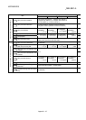
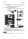
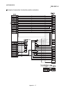
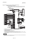
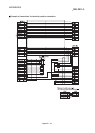
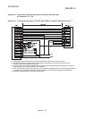
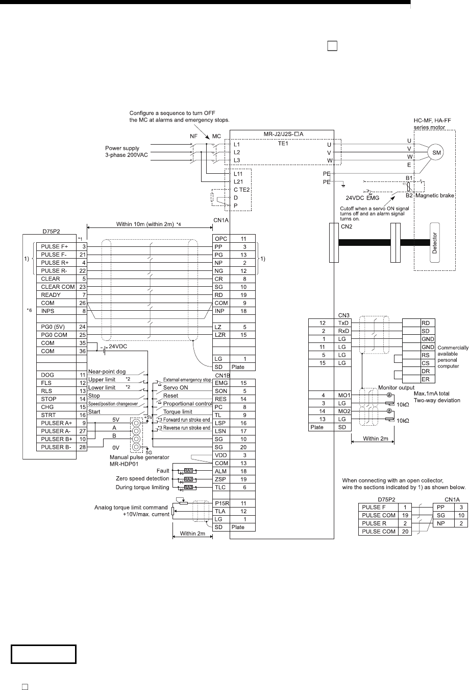
Appendix 5.2 Connection example of D75P2 and MR-J2/J2S- A
(Differential driver (Open collector)) *
5
In the following diagram, connection for absolute position restoration has not been
made. When making the connection for absolute position restoration, refer to the
following page.
*1 Assignment of the pin numbers of the connector of the D75P2 is the same for axis 1 and axis 2.
*2 The upper limit (FLS) and lower limit (RLS) of the D75P2 are used for zero point return retry function.
Set these inside the limit switches for the servo.
*3 Limit switch for servo (stopping).
*4 The distance between the controller and amplifier is indicated.
The distance must be within 2m with the open collector.
*5 Use “Logic selection for pulse output to the drive unit” specified in detailed parameter 1 to match the logic (positive or negative
logic) between the D75P2 and the servo amplifier. The initial setting of D75P2 is a positive logic.
*6 There is no need to wire the in-position signal. (It is output as in-position signal (RX(n+1)4, RX(n+4)4) but it is not used for internal
processes of the D75P2.)
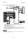
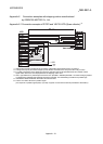
REMARK
The AD75C20SNJ2 cable (for differential driver) can be used for the connection between the D75P2 and MR-J2/J2S-
A. (Refer to section "2.2 List of configuration devices.")