


3 - 36
MELSEC-
A
3 SPECIFICATIONS AND FUNCTIONS
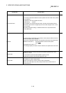
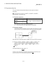
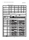
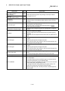
Output specifications
Signal name
Rated load
voltage
Operating load
voltage range
Max. load
current/inrush
current
Max. voltage
drop at ON
Leakage
current at
OFF
Response
time
Deviation counter clear
(CLEAR)
5 to 24VDC 4.75 to 30VDC
0.1A/1 point/0.4A
10ms or less
1VDC (TYP)
2.5VDC (MAX)
0.1mA or less
2ms or less
(resistance
load)
Servo ON
Proportional control (ABS data
transfer mode)
Torque limit (ABS data request)
5 to 24VDC 4.75 to 30VDC
0.1A/1 point/0.4A
10ms or less
1VDC (TYP)
2.5VDC (MAX)
0.1mA or less
2ms or less
(resistance
load)
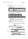
Open collector connection
Pulse output F (PULSE F)
Pulse output R (PULSE R)
5 to 24VDC 4.75 to 30VDC
50mA/1
point/200mA 10ms
or less
0.5VDC (TYP) 0.1mA or less —
Differential driver connection
Pulse output F (+/-) (PULSE F+/-)
Pulse output R (+/-) (PULSE R+/-)
Differential driver equivalent to AM26C31
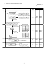
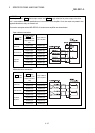
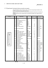
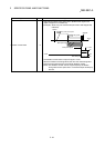
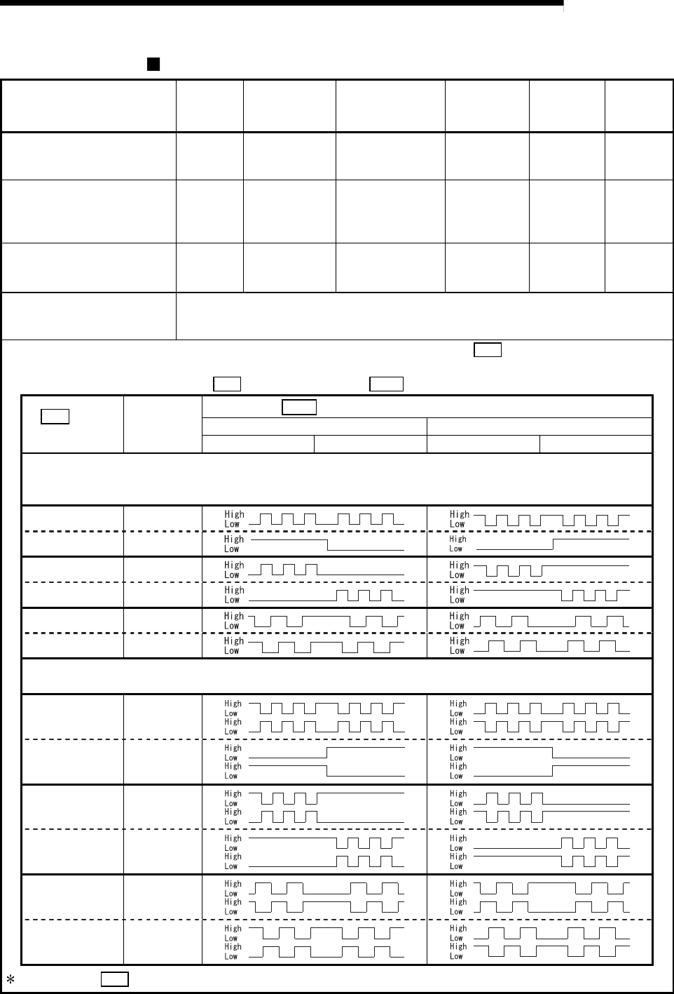
Select the PULSE/SIGN type, CW/CCW type, and A phase/B phase type using the parameter ( Pr.5 Pulse output mode) according to
the drive unit specifications.
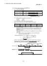
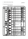
The relation of the pulse output with the " Pr.5 Pulse output mode" and " Pr.24 Logic selection for pulse output to the drive unit":
Pr.5 Pulse
output mode
*1
Terminal
name
Pr.24 Logic selection for pulse output to the drive unit
Positive logic Negative logic
Forward run Reverse run Forward run Reverse run
Open collector connection
The voltage of a terminal having the PULSE COM terminal as a reference is shown.
(The transistor output becomes OFF to High and ON to Low.)
PULSE PULSE F
SIGN PULSE R
CW PULSE F
CCW PULSE R
A phase PULSE F
B phase PULSE R
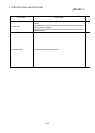
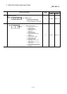
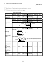
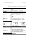
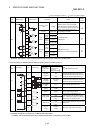
Differential driver connection
The voltage of a terminal having the differential driver common terminal as a reference is shown.
PULSE
PULSE F+
PULSE F-
SIGN
PULSE R+
PULSE R-
CW
PULSE F+
PULSE F-
CCW
PULSE R+
PULSE R-
A phase
PULSE F+
PULSE F-
B phase
PULSE R+
PULSE R-
1: For details on " Pr.5 Pulse output mode", refer to "Section 5.2.1, Basic parameters 1".