


4 - 16
MELSEC-
A
4 INSTALLATION, WIRING AND MAINTENANCE OF THE PRODUCT
4.5 Wiring/connection
This section explains the wiring and connection of the D75P2. "External wiring
insusceptible to noise" and "correct connection" are among the conditions to fully
exhibit the D75P2 functions and ensure high reliability for the system. To avoid
malfunctions due to noise and faults, accidents, etc. due to poor connection, perform
the external wiring/connection of the D75P2, paying attention to the following points as
well as "Section 4.1.3 Handling precautions".
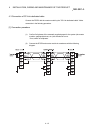
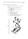
There are the following three wiring types for the D75P2.
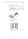
• Wiring of external device connection connector pins
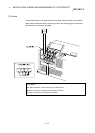
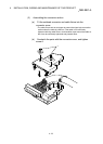
• Connection (removal) of connectors
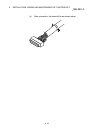
• Connection of CC-Link dedicated cables
4.5.1 Precautions for wiring/connection
(1) Always earth the FG terminal to the protective earth conductor. Failure to do so
may cause a malfunction.
(2) Wire the PLC correctly after confirming the rated voltage and terminal layout of
the product. Connection of a power supply different from the rating or improper
wiring can cause a fire or failure.
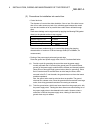
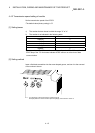
(3) Tighten the terminal screws to the specified torque.
Undertightening can cause a short circuit, fire or malfunction.
Overtightening can cause a drop, short circuit or malfunction due to damaged
screws or module.
Screw location Tightening torque range
Terminal block terminal screw (M3.5 screw) 0.59 to 0.88 N•m
Terminal block mounting screw (M4 screw) 0.78 to 1.18 N•m
(4) Completely turn off the externally supplied power used in the system when
installing or placing wiring.
Failure to do so may cause an electric shock or product damage.
(5) Perform wiring of the D75P2 correctly while checking the terminal arrangement.
(For the terminal arrangement of the external device connection connector, refer
to section
"3.7.2 Signal layout for external device connection connector.")
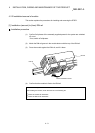
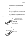
(6) Solder or crimp the external device connection connector correctly.
An improperly soldered or crimped connector may cause malfunctions.
(7) Be careful to avoid entry of chips, wiring dust and so on inside the D75P2.
Otherwise fire, failure or malfunction may be caused.
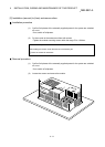
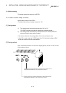
(8) Be sure to install a cover for the external device connection connector if no
external device is connected. Otherwise malfunction may be caused.
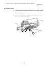
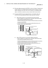
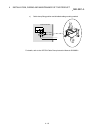
(9) Connect the external device connection connector and peripheral device
connection connector with the connector of the D75P2. Check that the connector
snaps. An improperly connected connector will cause poor continuity, possibly
causing erroneous inputs or outputs.