


6 - 15
MELSEC-
A
6 SEQUENCE PROGRAM USED FOR POSITIONING CONTROL
6.1.2 When QCPU (Q mode)/QnACPU is used
[1] System used in this chapter
An example of the sequence program explained in this chapter for use of the QCPU (Q
mode)/QnACPU is described for the following system.
Refer to the CC-Link Master Module User's Manual for details on the sequence
program for the entire CC-Link system.
For details on the dedicated instructions for the QCPU, refer to the CC-Link Master
Module User's Manual; for the QnACPU, refer to the QnACPU PROGRAMMING
MANUAL (Special Function module).
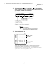
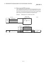
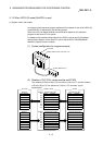
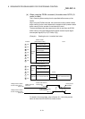
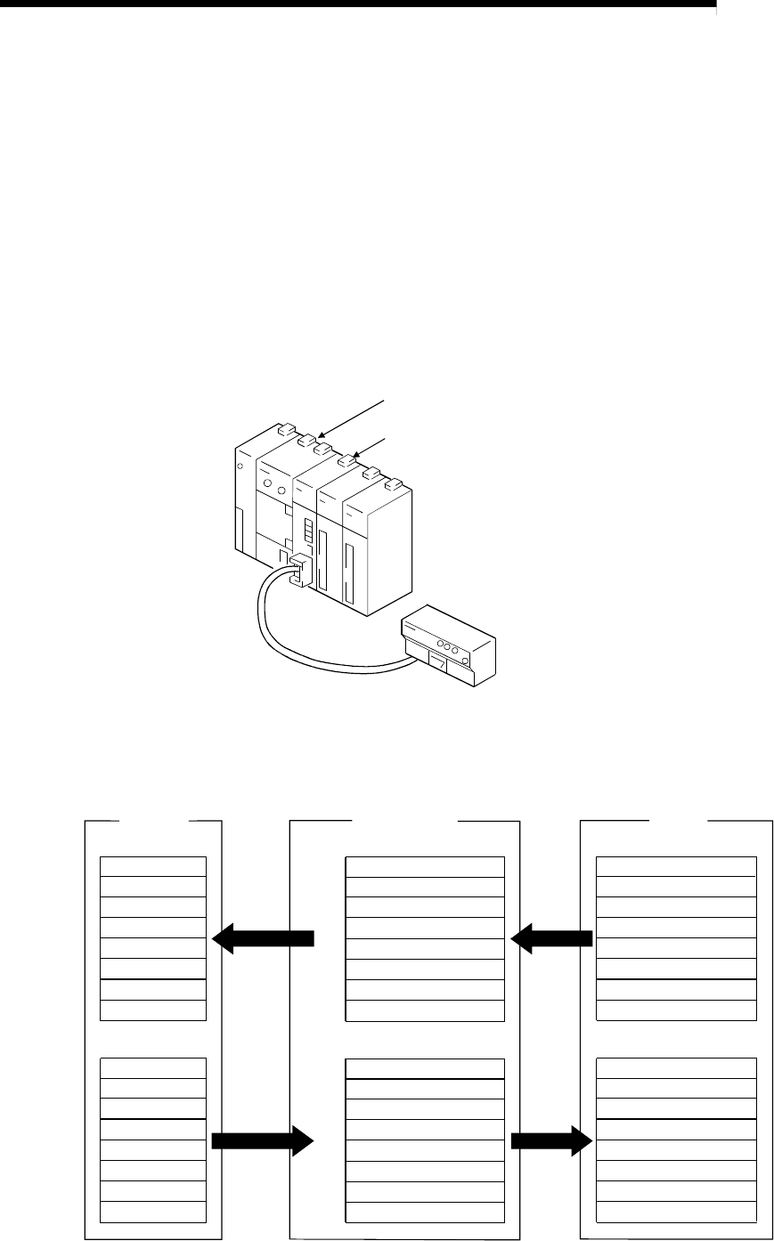
(1) System configuration for program example
PLC CPU
Master station (X0 to X1F/Y0 to Y1F)
D75P2 (Station No. 1)
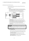
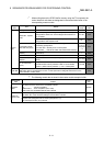
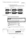
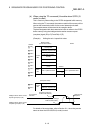
(2) Relation of PLC CPU, master module and D75P2
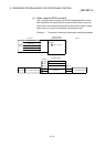
The contents of RXn0 to RX(n+7)F are read to X100 to X17F, and the contents
of RYn0 to RY(n+7)F are written into Y100 to Y17F and used. (Cyclic
transmission)
RYn0 to RYnF
RY(n+1)0 to RY(n+1)F
RY(n+2)0 to RY(n+2)F
RY(n+3)0 to RY(n+3)F
RY(n+4)0 to RY(n+4)F
RY(n+5)0 to RY(n+5)F
RY(n+6)0 to RY(n+6)F
RY(n+7)0 to RY(n+7)F
PLC CPU
Master module
D75P2
RXn0 to RXnF
RX(n+1)0 to RX(n+1)F
RX(n+2)0 to RX(n+2)F
RX(n+3)0 to RX(n+3)F
RX(n+4)0 to RX(n+4)F
RX(n+5)0 to RX(n+5)F
RX(n+6)0 to RX(n+6)F
RX(n+7)0 to RX(n+7)F
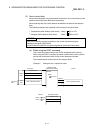
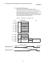
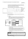
Remote input (RX)
Device X
X100 to X10F
X110 to X11F
X120 to X12F
X130 to X13F
X140 to X14F
X150 to X15F
X160 to X16F
X170 to X17F
E0
H
E1H
Remote input (RX)
Address
E2
H
E3
H
E4
H
E5
H
E6H
RXn0 to RXnF
RX(n+1)0 to RX(n+1)F
RX(n+2)0 to RX(n+2)F
RX(n+3)0 to RX(n+3)F
RX(n+4)0 to RX(n+4)F
RX(n+5)0 to RX(n+5)F
RX(n+6)0 to RX(n+6)F
RX(n+7)0 to RX(n+7)FE7
H
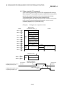
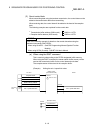
Remote output (RY)
Device Y
Y100 to Y10F
Y110 to Y11F
Y120 to Y12F
Y130 to Y13F
Y140 to Y14F
Y150 to Y15F
Y160 to Y16F
Y170 to Y17F
160
H
Remote output (RY)
Address
RYn0 to RYnF
RY(n+1)0 to RY(n+1)F
RY(n+2)0 to RY(n+2)F
RY(n+3)0 to RY(n+3)F
RY(n+4)0 to RY(n+4)F
RY(n+5)0 to RY(n+5)F
RY(n+6)0 to RY(n+6)F
RY(n+7)0 to RY(n+7)F
161
H
162
H
163
H
164H
165
H
166
H
167H