


1 - 19
MELSEC-
A
1 PRODUCT OUTLINE
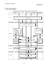
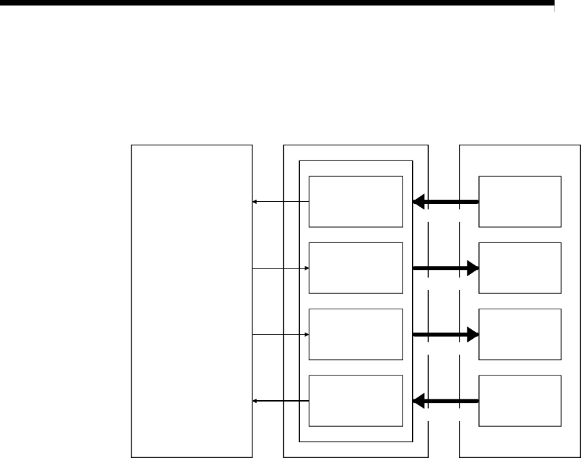
1.3.1 Cyclic transmission
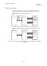
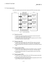
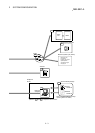
This section explains cyclic transmission between the D75P2 and master module.
PLC CPU Master module
D75P2
Buffer memory
Remote input
(RX)
Remote output
(RY)
Remote register
(RWw)
Remote register
(RWr)
Remote input
(RX)
Remote output
(RY)
Remote register
(RWw)
Remote register
(RWr)
Link scan
Link scan
Link scan
Link scan
1)2)
3) 4)
5) 6)
8) 7)
Fig. 1.7 Cyclic transmission
(1) Remote input (RX)
1) The data of the remote input (RX) of the D75P2 are stored into the buffer
memory of the master module every link scan.
2) The input data stored in the master module are imported to the PLC CPU by
the FROM command or automatic refresh.
(2) Remote output (RY)
3) The data of the remote output (RY) of the D75P2 are written to the buffer
memory of the master module by the TO command or automatic refresh.
4) The output data stored in the master module are sent to the D75P2 every link
scan.
(3) Remote register (RWw)
5) The data of the remote register (RWw) of the D75P2 are written to the buffer
memory of the master module by the TO command or automatic refresh.
6) The transmission data stored in the master module are sent to the D75P2
every link scan.
(4) Remote register (RWr)
7) The data of the remote register (RWr) of the D75P2 are stored into the buffer
memory of the master module every link scan.
8) The reception data stored in the master module are imported to the PLC CPU
by the FROM command or automatic refresh.