


7 - 5
MELSEC-
A
7 MEMORY CONFIGURATION AND DATA PROCESS
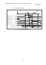
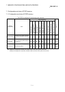
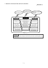
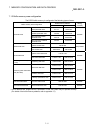
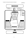
7.1.2 Buffer memory area configuration
The D75P2 buffer memory is configured of the following types of areas.
Buffer memory area configuration
Buffer memory address
Writing
possibility
Axis 1 Axis 2
Parameter area
Basic parameter area 0 to 14 150 to 164
Possible
Detailed parameter area 15 to 66 165 to 216
Zero point return basic
parameter area
70 to 78 220 to 228
Zero point return detailed
parameter area
79 to 89 229 to 239
Monitor data area
System monitor area 450 to 799
Not possible
Axis monitor area 800 to 899 900 to 999
Control data area
System control data area 1100 to 1149
Possible
Axis control data area 1150 to 1199 1200 to 1249
Positioning data area (No.1
to 100)
Positioning data area 1300 to 2299 2300 to 3299
Possible
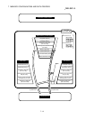
Positioning start information
area (No.7000)
Start block data area
4300 to 4349 4550 to 4599
4350 to 4399 4600 to 4649
Condition data area 4400 to 4499 4650 to 4749
Indirectly specification area 4500 to 4549 4750 to 4799
PLC CPU memo area
PLC CPU memo area 5050 to 5099
Possible
Block transmission area
Block transmission area 5100 to 6109
Possible
* Use of address Nos. skipped above is prohibited. If used, the system may not operate correctly.
(For details of the buffer memory address, refer to appendix 13.)