


7 - 6
MELSEC-
A
7 MEMORY CONFIGURATION AND DATA PROCESS
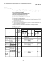
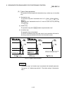
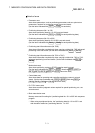
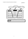
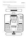
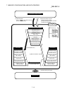
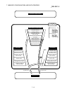
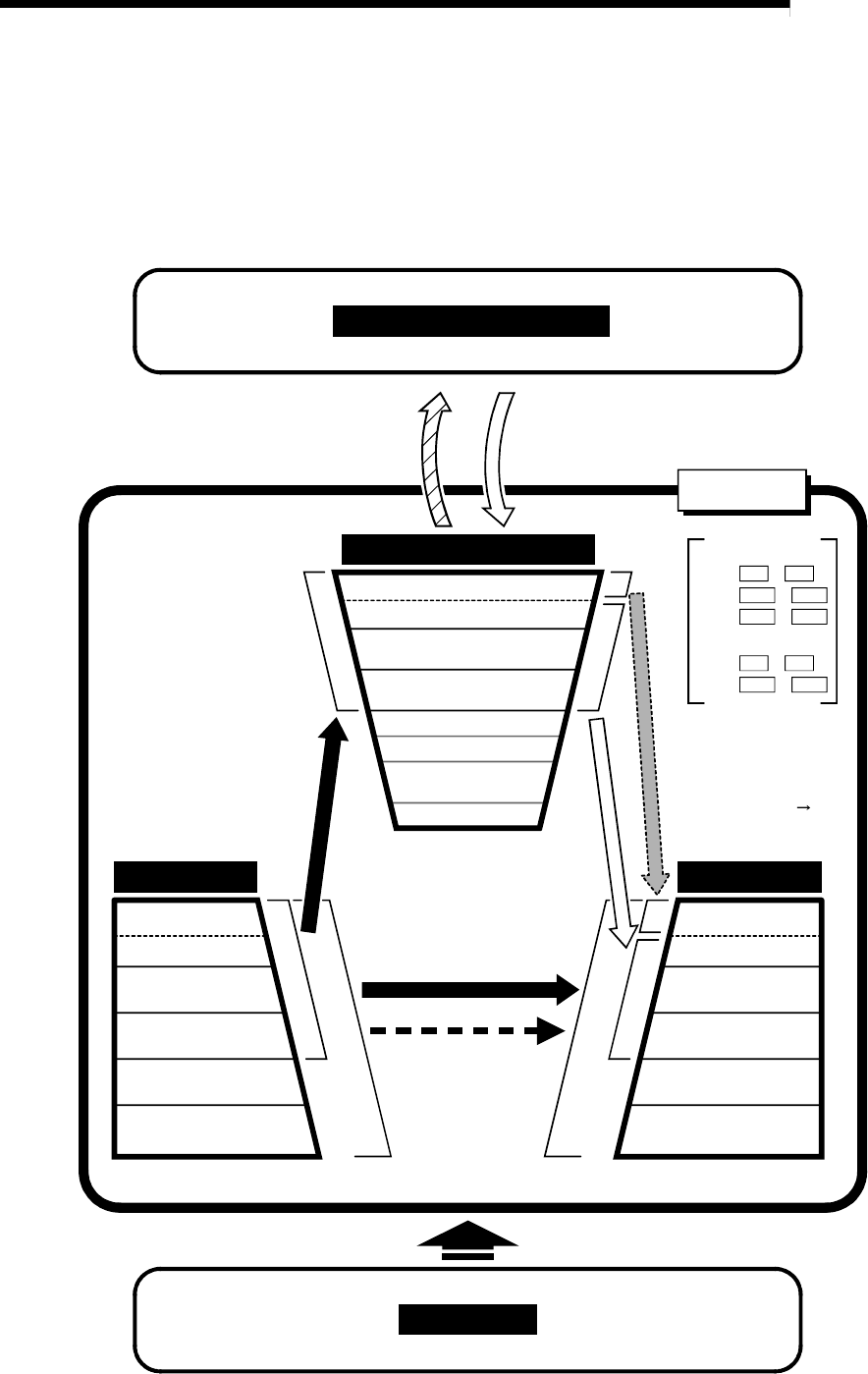
7.2 Data transmission process
The data is transmitted between the D75P2 memories with steps (1) to (10) shown
below.
The data transmission patterns numbered (1) to (10) on the right page correspond
to the numbers (1) to (10) on the left page.
Parameter area (a)
Parameter area (b)
Positioning data area
(No.1 to 100)
Positioning data area
(No.1 to 100)
Positioning start information area
(No.7000)
Positioning start information
area (No.7000)
Positioning start information
area (No.7001 to 7010)
PLC CPU memory area
Block transmission area
Monitor data area
Control data area
Buffer memory, Remote Resister
PLC CPU + MASTER MODULE
Peripheral device
Flash ROM ROM
Positioning data area
(No.101 to 600)
Parameter area (a)
Parameter area (b)
Positioning data area
(No.1 to 100)
Positioning start information
area (No.7000)
Positioning start information
area (No.7001 to 7010)
Positioning data area
(No.101 to 600)
Parameter area (a)
Parameter area (b)
OS memory
(5) Flash ROM read 1)
(5) Flash ROM request (read)
(1) Power ON reset
(3) TO command
(3)Write(4)Read
(1) Power ON reset
D75P2
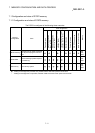
Parameter area (a)
Pr.6
Pr.1
Pr.10
Pr.25
Pr.45 Pr.58
Parameter area (b)
Pr.9
Pr.7
Pr.26 Pr.44
to
to
to
to
to
(2) Remote station READY
signal
[RX(n+7)B] OFF ON