


9 - 53
MELSEC-
A
9 MAIN POSITIONING CONTROL
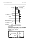
Restrictions
<Common to INC mode and ABS mode>
(1) If “continuous path control” is specified for “ Da.1 Operation pattern”, an error
“continuous path control not possible” (error code: 516) occurs, resulting in a
failure to start. (In the speed/position changeover control, “continuous path
control” cannot be set.)
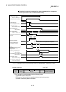
(2) If “continuous path control” is specified for “
Da.1 Operation pattern” of the
positioning data immediately before, “speed/position changeover control”
cannot be specified for “
Da.2 Control method” in the positioning data. (For
example, if the operation pattern of positioning data No. 1 is “continuous path
control,” “speed/position changeover control” cannot be specified for
positioning data No. 2.) If this setting is given, an error “continuous path
control not possible” (error code: 516) occurs, resulting in deceleration and
stop.
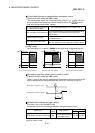
(3) The software stroke limit range check under speed control is performed only if
“1: update current feed value” is specified for “
Pr.22 Current feed value
during speed control.” At this time, if the movement amount exceeds the
software stroke limit range during speed control, an error “start outside stroke
limit +/-” (error code: 507/508) occurs at the timing of the change to position
control, resulting in deceleration and stop.
If the “degree” unit is selected, the software stroke limit range check is not
performed.
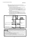
<In INC mode only>
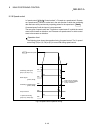
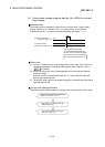
(4) If the position control movement amount specified for “
Da.5
Positioning
address/movement amount” is smaller than the deceleration distance from
“
Da.7 Command speed,” deceleration occurs when the speed/position
changeover signal is supplied.
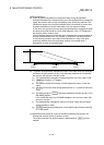
(5) Turn ON the speed/position changeover signal in a stable-speed area
(constant-speed state). If it is turned ON during acceleration, a warning
“speed/position changeover signal ON during acceleration” (warning code:
508) occurs due to large variation in the accumulating pulses.
(6) Do not turn ON the speed/position changeover signal during speed change if
the servomotor is used. (Turn the speed/position changeover signal ON in the
stable-speed area (constant-speed state).) The actual movement amount after
switching is the “set movement amount + amount of accumulated pulses.” If
the signal is turned ON during acceleration or deceleration, there is variation in
the stopping position due to a large variation in the amount of accumulated
pulses. If “
Da.7 Command speed” varies even if “ Md.38 Speed/position
changeover control positioning amount” is the same, the amount of
accumulated pulses varies and therefore the stopping position varies.
(7) A software stroke limit range check during speed control is performed only
when the following (a) and (b) are satisfied.
(a) The "
Pr.22
Current feed value during speed control" setting is "1: Update
current feed value"
If the setting is other than "1: Update current feed value" and the movement
amount exceeds the software stroke limit range during speed control, an
error (error code: 507 or 508) will occur at the point of switching to position
control, and the machine will decelerate to a stop.
(b) "
Pr.1
Unit setting" is other than "2: degree"
In the "degree" unit, the software stroke limit range check is not performed.