


Appendix - 48
MELSEC-
A
APPENDICES
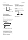
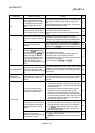
ZERO POINT RETURN METHOD
The zero point return methods are shown
below. The method used depends on the
machine structure, stopping accuracy, etc.
Machine zero point returns can be carried out
when the zero point return parameters are
written.
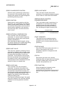
1) Near-point dog method.
2) Stopper stop method.
3) Count method.
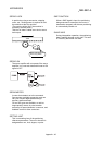
ZERO POINT RETURN PARAMETER
This parameter is required when returning to
the zero point. It is determined by the machine
side design, so subsequent changes of this
parameter must be accompanied by changes
in the machine design.
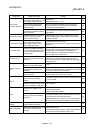
The zero point is the reference for positioning
operations, so if the zero point is lost due to a
power failure during positioning, or because
the power is turned OFF and the machine is
moved manually, etc., it can be restored by
carrying out a machine zero point return.
When a machine zero point return command is
issued, the machine will move in search of the
near-point dog regardless of the current value,
and will stop at the zero point. At this time, the
current value will be rewritten to the zero point
address. Data cannot be written during
positioning. With the D75P2, data is always
written for all axes (from 1, 2 axis).
Refer to the term "NEAR-POINT DOG".
ZERO POINT RETURN REQUEST
This signal turns ON when there is an error
with the D75P2. It will turn ON in the following
situations.
1) When the remote station READY signal
turns from OFF to ON.
2) When the machine zero point return starts.
3) When the drive unit READY signal turns
from ON to OFF.
The user judges whether to carry out a
machine zero point return in the above
situations.
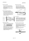
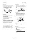
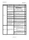
ZERO POINT SHIFT FUNCTION
The zero point position can be shifted to the
plus or minus direction by executing a machine
zero point return and determining a shift
amount for the position at the completion of
the machine zero point return.
A zero point can be set at a position besides
the zero point position, or outside the dog
switch.
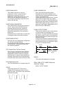
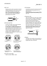
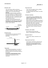
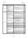
ZERO POINT SIGNAL
Indicates PG0 (detected once per rotation) of
the pulse generator (encoder). Also called a Z
phase.
Refer to "PULSE GENERATOR".
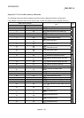
PG0
Feedback
pulses
1 axis rotation