


3 - 38
MELSEC-
A
3 SPECIFICATIONS AND FUNCTIONS
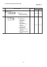
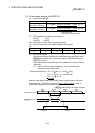
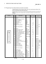
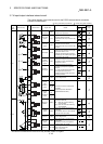
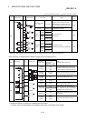
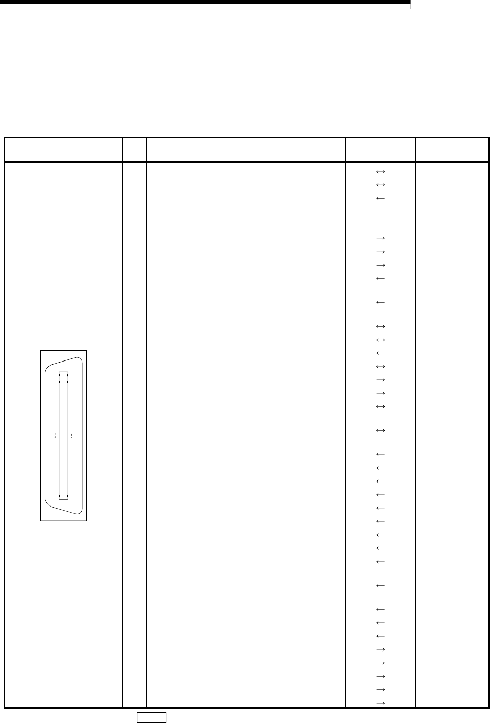
3.7.2 Signal layout for external device connection connector
The specifications of the connector section, which is the input/output interface for the
D75P2 and external device, are shown below.
The signal layout for the D75P2 external device connection connector (for one axis) is
shown.
(The signal layout for the external device connection connector is the same for axis 1
to axis 2.)
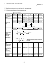
Pin layout
Pin
No.
Signal name
Signal direction
D75P2 – external
Connection
destination
1836
119
36 Common COM
(External device)
35 Common COM
(External device)
34 ABS transmission data READY TLC
Drive unit
33 Common (ABS IN) COM – Drive unit
32 Common (ABS OUT) COM – Drive unit
31 ABS request ABSR
Drive unit
30 ABS transfer mode ABSM
Drive unit
29 Servo ON SON
Drive unit
28 Manual pulse generator PULSER B–
Manual pulse
generator
27 Manual pulse generator PULSER A–
Manual pulse
generator
26 Common COM
Drive unit
25 Zero point signal common PG0 COM
Drive unit
24 Zero point signal (+5V) PG0 (5V)
Drive unit
23 Deviation counter clear common CLEAR COM
Drive unit
22 Pulse sign (differential driver –) PULSE R–
Drive unit
21 Pulse output (differential driver –) PULSE F–
Drive unit
20 Pulse sign common
(Open collector)
PULSE COM
Drive unit
19 Pulse output common
(Open collector)
PULSE COM
Drive unit
18 ABS data bit 1 ZSP
Drive unit
17 ABS data bit 0 D01
Drive unit
16 External start signal * STRT
(External device)
15 Speed/position changeover signal CHG
(External device)
14 Stop signal STOP
(External device)
13 Lower limit signal RLS
Limit switch
12 Upper limit signal FLS
Limit switch
11 Near-point dog signal DOG
Near-point dog
10 Manual pulse generator PULSE B+
Manual pulse
generator
9 Manual pulse generator PULSE A+
Manual pulse
generator
8 In-position signal INPS
Drive unit
7 Drive unit READY READY
Drive unit
6 Zero point signal (+24V) PG0 (24V)
Drive unit
5 Deviation counter clear CLEAR
Drive unit
4 Pulse sign (differential driver +) PULSE R+
Drive unit
3 Pulse output (differential driver +) PULSE F+
Drive unit
2 Pulse sign (Open collector) PULSE R
Drive unit
1 Pulse output (Open collector) PULSE F
Drive unit
* The signal application follows "
Pr.43
External start function selection".