


3 - 40
MELSEC-
A
3 SPECIFICATIONS AND FUNCTIONS
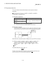
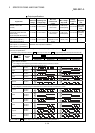
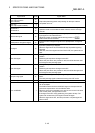
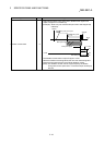
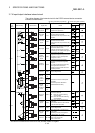
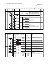
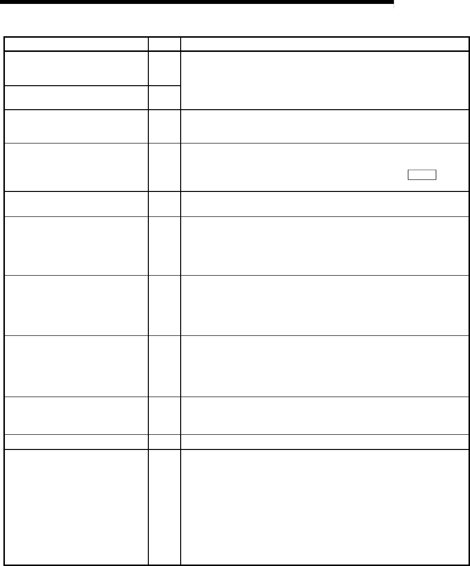
Signal name Pin No. Signal details
Pulse sign common
Pulse output common
(Open collector)
20
19
Output the positioning pulses and pulse sign for the open collector
compatible drive unit.
Pulse sign
Pulse output (Open collector)
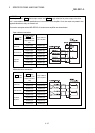
2
1
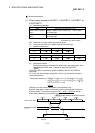
ABS data bit 1
ABS data bit 0
18
17
ABS data to be transferred from the servo to the D75P2 during the ABS
operation mode. bit 0 indicates the lower-order bit, and bit 1 the high-
order bit.
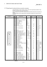
External start signal 16
Use as the positioning start, speed change request and skip request
input signal from an external source.
Set which function to use the external start signal with in "
Pr.43
External start function selection".
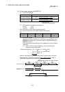
Speed/position changeover signal 15
Input the control changeover signal for the speed/position changeover
control.
Stop signal 14
Input when positioning is stopped.
When this signal turns ON, the D75P2 will stop the positioning being
executed.
After that, even if this signal turns from ON for OFF, the system will not
start.
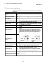
Lower limit signal 13
This signal is input from the limit switch installed at the stroke lower limit
position.
Positioning will stop when this signal turns OFF.
When zero point return retry function is valid, this will be the lower limit
for finding the near-point dog signal.
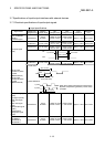
Upper limit signal 12
This signal is input from the limit switch installed at the stroke upper limit
position.
Positioning will stop when this signal turns OFF.
When zero point return retry function is valid, this will be the upper limit
for finding the near-point dog signal.
Near-point dog signal 11
Use this for detecting the near-point dog during machine zero point
return.
The near-point dog signal is detected at turning from OFF to ON.
In-position signal 8
Input the in-position signal from the drive unit.
Drive unit READY 7
This signal turns ON when the drive unit is normal and the feed pulse
can be accepted.
The D75P2 checks the drive unit READY signal, and outputs the zero
point return request when not in the READY state.
When the drive unit is inoperable, such as if an error occurs in the drive
unit's control power, this signal will turn OFF.
If this signal turns OFF during positioning, the system will stop. The
system will not start even if this signal is turned ON again.
When this signal turns OFF, the zero point return complete signal will
also turn OFF.