


8 - 16
MELSEC-
A
8 ZERO POINT RETURN CONTROL
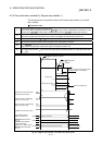
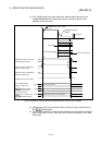
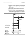
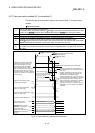
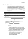
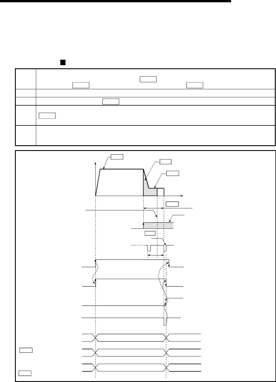
8.2.7 Zero point return method (5): Count method 1)
The following shows an operation outline of the "count method 1)" zero point return
method.
Operation chart
1)
The machine starts a machine zero point return.
(The machine starts acceleration specified in "
Pr.53
Zero point return acceleration time selection" in the
direction set in "
Pr.46
Zero point return direction", and moves at " Pr.48 Zero point return speed".)
2) The machine detects near-point dog ON and starts deceleration.
3)
The machine decelerates to "
Pr.49 Creep speed" and then moves at the creep speed.
4)
At the first zero point signal issued after the machine has moved the movement amount set in
"
Pr.52 Setting for the movement amount after near-point dog ON" after near-point dog ON, pulse output
from the D75P2 stops and "deviation counter clear output" is output to the drive unit.
5)
After the completion of "deviation counter clear output", the zero point return complete flag (RX(n+2)0,
RX(n+5)0) turns from OFF to ON and the zero point return request flag (RX(n+1)F, RX(n+4)F) turns from
ON to OFF.
t
ON
OFF
ON
OFF
OFF
ON
0
V
ON
Pr. 49 Creep speed
Pr. 48 Zero point return speed
Pr.52 Setting for the movement amount
after near-point dog ON
Md.44 Movement amount after near-point dog ON
Zero point signal
Near-point dog OFF
Machine zero point return start
(Positioning start signal)
Standing by
In zero point return
Axis operation status
[RWrn+7, RWrn+15]
Inconsistent
Value the machine moved is stored
Zero point address
Value of *1.
Deviation counter clear output
Standing by
Inconsistent
Zero point return request flag
[RX(n+1)F, RX(n+4)F]
Zero point return complete flag
[RX(n+2)0, RX(n+5)0]
Md.30 Machine feed value
Md.44 Movement amount
after near-point dog ON
Current feed value
[RWrn+0 to 1, RWrn+8 to 9]
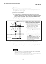
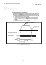
*
1
1) 2) 3) 4) 5)
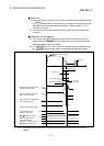
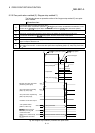
Adjust the movement amount after
activation at the near-point dog to
the center of the high zero point
signal interval as far as possible.
If the movement amount setting
after activation at the near-point dog
interferes with the zero point signal,
the machine zero point return stopping
position may deviate by a revolution of
the servomotor.
First zero point after travel by " Pr. 52
Setting for the movement amount
after near-point dog ON"
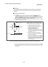
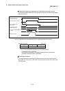
There is no problem even if deactivation at
the near-point dog occurs during machine zero
point return.
However, deactivation at the near-point dog
should be as far from the zero position as
possible, due to the following reason.
If deactivation at the near-point dog occurs at
the end of machine zero point return, the motor
is not stopped in the second action until the
upper or lower limit is reached when repetitive
machine zero point return cycles occur.
If the zero point return retry function has been
invalidated, an error is caused upon detection
of the limit.
Equivalent
to 1 servo
motor
rotation
Fig. 8.11 Count method1) machine zero point return