


5 - 21
MELSEC-
A
5 DATA USED FOR POSITIONING CONTROL
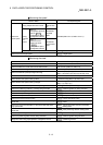
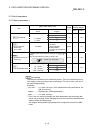
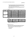
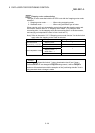
Item
Setting value, setting range
Default
value
Setting value buffer
memory address
Value set with peripheral
device
Value set with sequence
program
Axis 1 Axis 2
Pr.5
Pulse output mode
0: PULSE/SIGN mode 0
1 4 154
1: CW/CCW mode 1
2: A phase/B phase
(multiple of 4)
2
3: A phase/B phase
(multiple of 1)
3
Pr.6
Rotation direction
setting
0: Current value increment
with forward run pulse
output
0
0 5 155
1: Current value increment
with reverse run pulse
output
1
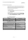
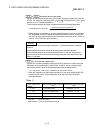
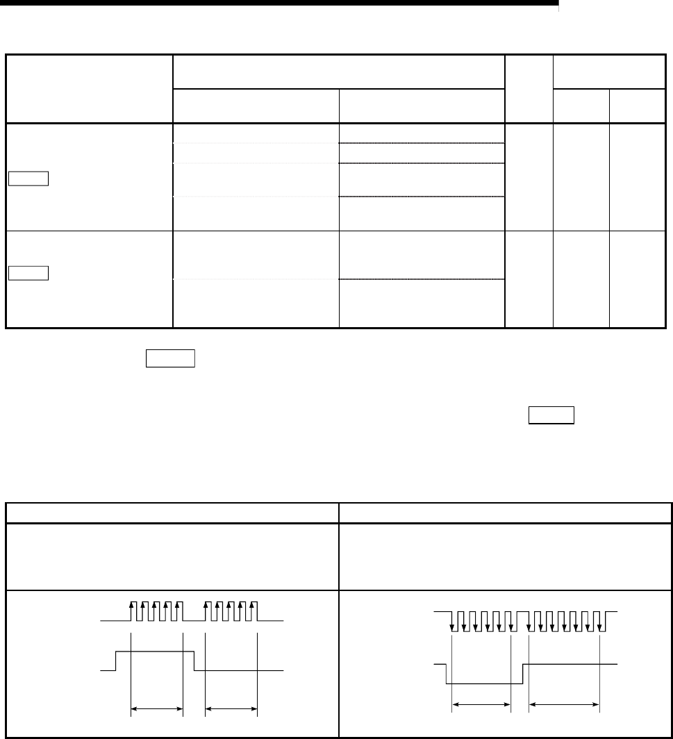
Pr.5
Pulse output mode
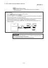
Set the pulse output mode to match the servo amplifier being used.
The pulse positive logic and negative logic is changed with "
Pr.24
Logic
selection for pulse output to the drive unit ".
An example of the pulse output mode for positive logic is shown below.
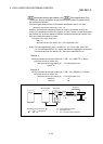
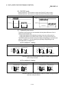
(1) PULSE/SIGN mode
Positive logic Negative logic
Forward run and reverse run are controlled with the ON/OFF
of the direction sign (SIGN).
The motor will forward run when the direction sign is HIGH.
The motor will reverse run when the direction sign is LOW.
Forward run and reverse run are controlled with the ON/OFF
of the direction sign (SIGN).
The motor will forward run when the direction sign is LOW.
The motor will reverse run when the direction sign is HIGH.
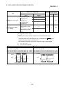
PULSE
SIGN
Forward
run
Reverse
run
Move in + direction Move in - direction
PULSE
SIGN
Forward
run
Reverse
run
Move in + direction Move in - direction