


3 - 43
MELSEC-
A
3 SPECIFICATIONS AND FUNCTIONS
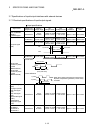
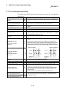
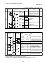
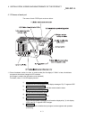
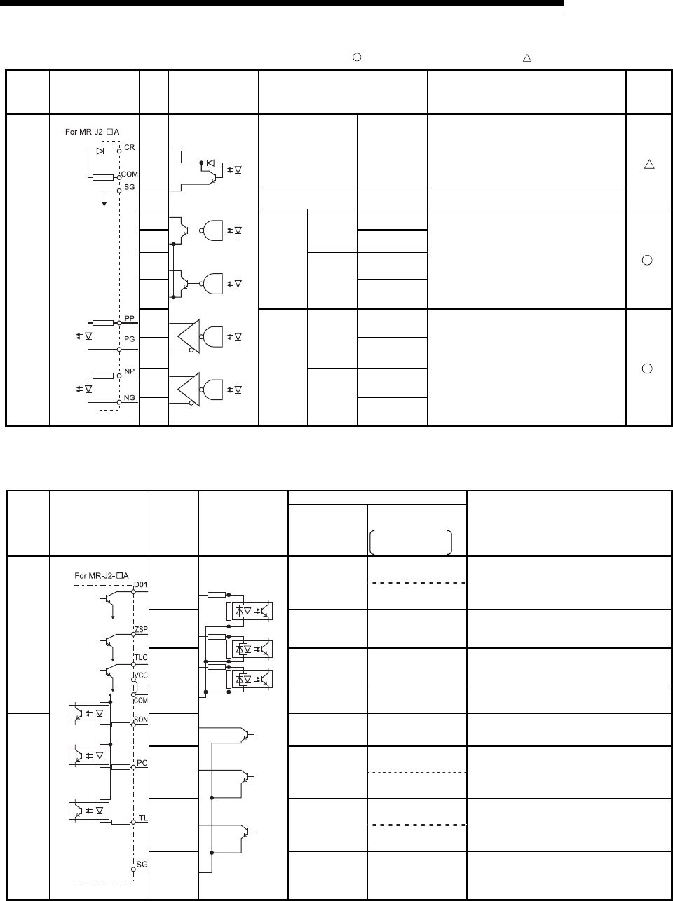
: Wiring is necessary in positioning. : Perform wiring when necessary.
Input/out
-put
class
External wiring
Pin
No.
Internal circuit Signal name Details
Need for
wiring
Output
5
Deviation counter
clear
CLEAR
• Signal that resets the droop pulses of the
deviation counter on the drive unit side.
• After completion of a machine zero point
return, this signal is output by the OS of the
D75P2. (Cannot be output by the user.)
23 Common CLEAR COM • Load voltage 5V to 24VDC
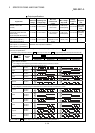
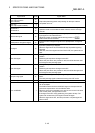
1
Open
collector
CW
A phase
PULSE
PULSE F
Open collector output
(5VDC/24VDC)
*
19 PULSE COM
2
CCW
B phase
SIGN
PULSE R
20 PULSE COM
3 (+)
Differential
driver
CW
A phase
PULSE
PULSE F+
Differential driver output
(Differential driver equivalent to AM26LS31)
*
21 (–) PULSE F–
4 (+)
CCW
B phase
SIGN
PULSE R+
22 (–) PULSE R–
* Select the open collector output or differential driver output according to the drive unit being used.
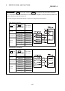
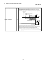
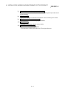
When configuring an absolute position detection system, perform the following wiring.
I/O
division
External wiring Pin No. Internal circuit
Signal name (Abbreviation)
Details
(When ABS transfer mode is ON)
When ABS
transfer mode is
ON *1
When ABS transfer
mode is OFF *2
Top: MR-H
Bottom: MR-J2/J2S
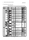
Input
17
ABS data
bit 0 [D01]
Positioning complete
[PF]
• Signal that indicates the low-order bit of the
two ABS data bits transferred from the servo
to the D75P2 during the ABS transfer mode.
Positioning complete
[D01]
18
ABS data
bit 1 [ZSP]
Zero speed
[ZSP]
• Signal that indicates the high-order bit of the
two ABS data bits transferred from the servo
to the D75P2 during the ABS transfer mode.
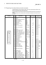
34
ABS transmission
data READY
[TLC]
Torque limiting
[TLC]
• Signal that indicates that transmission data is
ready during the ABS transfer mode.
33
Common
[COM]
Common
[COM]
• Input/output voltage 24VDC. (+24V side)
Output
29
Servo ON
[SON]
Servo ON
[SON]
• Signal that powers on the base circuit of the
servo to make it ready to operate.
30
ABS transfer
mode [ABSM]
–
[D13]
• Used to select the ABS transfer mode
• While this signal is ON, the "ABS data bit 0
[D01]", "ABS data bit 1 [ZSP]" and "ABS send
data READY [TLC]" signals are valid.
Proportional control
[PC]
31 ABS request
–
[D14]
• Signal that requests ABS data during the ABS
transfer mode.
Torque limiting
[PC]
32
Common
[COM]
Common
[COM]
• Input/output voltage 24VDC. (24G side)
*1 Indicates the signals during the ABS transfer mode.
*2 Indicates the signals in a normal (not in ABS transfer mode) status.
For details, refer to the Specifications and Installation Guide of the corresponding servo amplifier.