


Appendix - 44
MELSEC-
A
APPENDICES
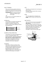
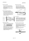
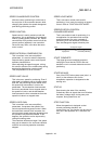
SPEED CHANGEOVER CONTROL
With this control, positioning is carried out to
the end point of the movement amount while
changing the speed at the speed changeover
point during positioning control.
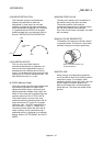
SPEED CONTROL
Speed control is mainly carried out with the
servomotor. It is an application for grindstone
rotation, welding speed, feedrate, etc. Speed
control differs from position control in that the
current position (address) is not controlled.
Drive units may differ, even when the same
motor is used.
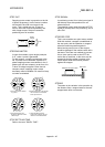
SPEED INTEGRAL COMPENSATION
This is one item in the servo amplifier's
parameters. It is used to raise the frequency
response during speed control, and improve
transient characteristics.
When adjusting the speed loop gain, raising
this value is effective if the overshooting during
acceleration/deceleration remains large.
This compensation is set in ms units.
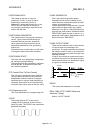
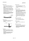
SPEED LIMIT VALUE
This is the max. speed for positioning. Even if
other data is mistakenly set to a higher speed
than this, the positioning will be carried out at
this speed limit value when it is set in the
parameters. The acceleration time becomes
the time to accelerate from a stopped state to
the speed limit value, and the deceleration
time becomes the time to decelerate from the
speed limit value to a stopped state.
SPEED LOOP GAIN
This is one item in the servo amplifier's
parameters. It expresses the speed of the
control response during speed control. When
the load inertia moment ratio increases, the
control system speed response decreases and
the operation may become unstable. If this
happens, the operation can be improved by
raising this setting value.
The overshoot will become larger if the speed
loop gain is raised too far, and motor vibration
noise will occur during operation and when
stopped.
SPEED LOOP MODE
This is one servo control mode used in
positioning. It is a mode for carrying out speed
control. Refer to "POSITION LOOP MODE".
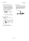
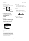
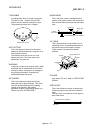
SPEED/POSITION CONTROL
CHANGEOVER MODE
This is one method used for positioning. It is
an application for operations such as high-
speed movement to a point unrelated to
positioning, then set dimension movement
from the changeover signal activation point.
Start
Changeover signal
High speed Increment positioning
START COMPLETE
This signal gives an immediate response
notifying the user that the D75P2 that was
started is now in a normal state and can start
positioning.
STARTING AXIS
One of the D75P2 axis system axes (axis 1 or
axis 2) or the reference axis for the
interpolation operation is designated as the
starting axis.
STATUS
Data showing the state of the machine.
Collectively refers to signals that turn ON when
the battery voltage drops, during zero point
requests, during dwell time, etc.
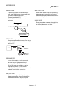
STEP FUNCTION
When the operation is designed so that
several positioning data Nos. are
consecutively run, this function can be used to
carry out a test operation for 1 data item at a
time.