


Appendix - 36
MELSEC-
A
APPENDICES
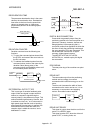
INPUT TERMINAL
This is a pin connector wired by the user for
inputting data to the D75P2 from an external
source. It is connected to the motor drive unit
or machine side.
This terminal is used to output the following.
DRIVE UNIT READY signal
STOP signal
, etc.
The input No. Xn is not directly related to the
program, so it is not used.
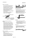
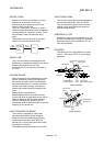
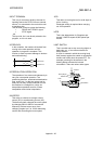
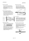
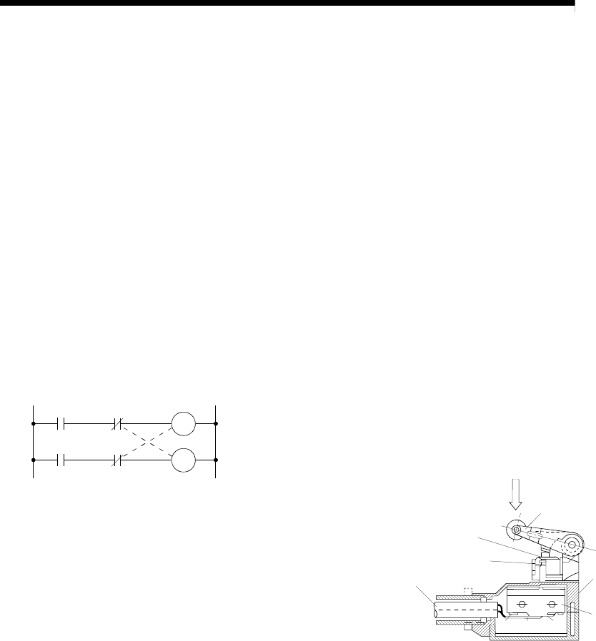
INTERLOCK
In this condition, the machine is blocked from
moving to the next operation until the
operation in progress is complete. This
function is used to prevent damage to devices
and malfunctioning.
Y1
Y0
Y0
Y1
Forward run
Reverse run
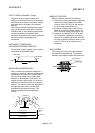
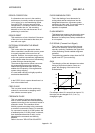
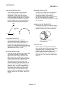
INTERPOLATION OPERATION
The operation of two motors simultaneously to
carry out a composite operation. The
positioning distance, acceleration/deceleration
time, speed, etc., for the two motors can be
freely set, but they will be combined to move
the machine in a straight line, circle, etc.
Interpolation operations consist of linear
interpolation and circular interpolation.
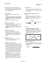
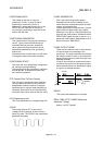
INVERTER
This refers to a device to change a direct
current (DC) to an alternating current (AC).
The device actually changes the motor speed
by changing 50Hz or 60Hz of commercial
frequency to direct current once, then
changing it again to a 5 to 120Hz alternating
current and controlling the motor speed.
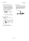
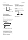
JOG
This refers to moving the tool in small steps at
a time. Inching.
Parameter setting is required when carrying
out JOG operation.
kPPS
This is the abbreviation for "kilopulses per
second". 80kPPS equals 80,000 pulses per
second.
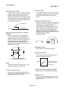
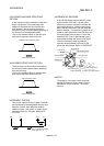
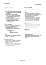
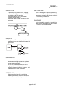
LIMIT SWITCH
This is a switch set to stop a moving object at
both ends, etc., of a movement device for
safety reasons.
A circuit is created in which the moving body
itself presses against the switch to activate the
contact and forcibly shut the power OFF. For
example, pressing on the actuator in the
drawing below activates the internal
microswitch. There are various other types.
NC NO
COM
Push plunger
Actuator
Rubber cap
Lead
Case
Microswitch