


3 - 37
MELSEC-
A
3 SPECIFICATIONS AND FUNCTIONS
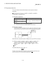
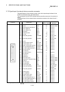
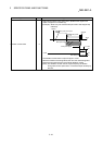
POINT
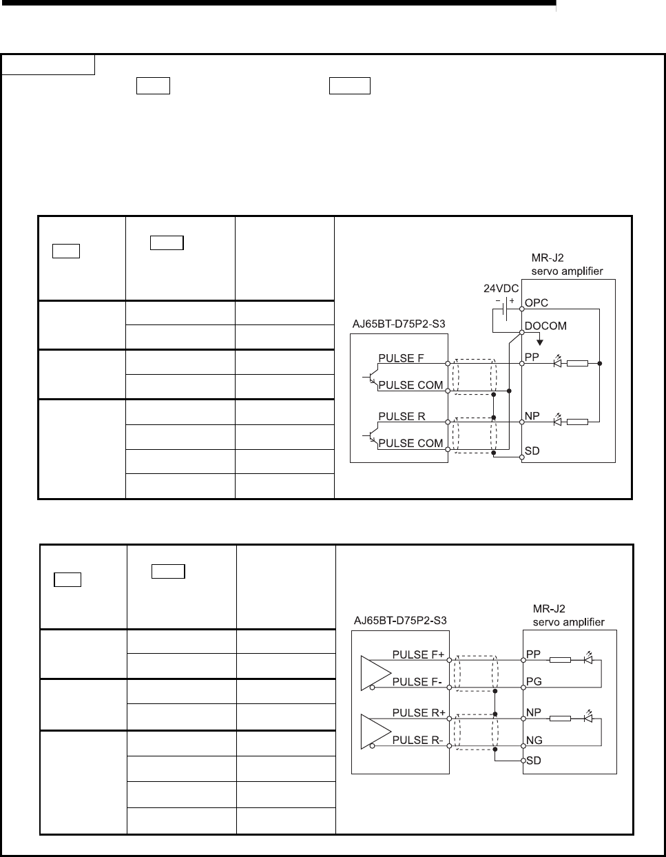
Set the parameters, " Pr.5 Pulse output mode" and " Pr.24 Logic selection for pulse output to the drive
unit", in accordance with the specifications of a connected servo amplifier. If not, the motor may rotate in the
opposite direction or may not rotate at all.
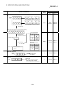
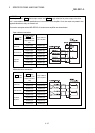
Connection examples with a MELSERVO-J2 series servo amplifier are shown below.
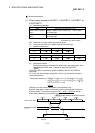
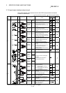
Open collector connection
Pr.5 Pulse
output mode
AJ65BT-D75P2-S3
( Pr.24 Logic
selection for pulse
output to the drive
unit)
Logic of MR-J2
servo amplifier
CW/CCW
Negative logic Negative logic
Positive logic Positive logic
PULSE/SIGN
Negative logic Negative logic
Positive logic Positive logic
A phase/
B phase
Negative logic Negative logic
Negative logic Positive logic
Positive logic Negative logic
Positive logic Positive logic
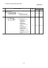
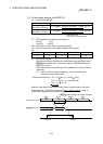
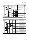
Differential driver connection
Pr.5 Pulse
output mode
AJ65BT-D75P2-S3
( Pr.24 Logic
selection for pulse
output to the drive
unit)
Logic of MR-J2
servo amplifier
CW/CCW
Negative logic Positive logic
Positive logic Negative logic
PULSE/SIGN
Negative logic Positive logic
Positive logic Negative logic
A phase/
B phase
Negative logic Negative logic
Negative logic Positive logic
Positive logic Negative logic
Positive logic Positive logic