


1 - 14
MELSEC-
A
1 PRODUCT OUTLINE
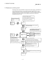
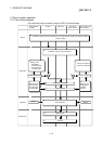
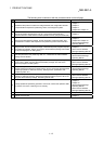
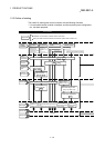
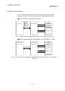
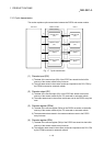
1.2.2 Outline of starting
The outline for starting each control is shown with the following flowchart.
* It is assumed that each module is installed, and the required system configuration,
etc., has been prepared.
Preparation
Control
functions
Main position-
ing control
Advanced posi-
tioning control
Zero point return
control
Manual control
·Position control
·Speed control
·Speed/position
changeover control
·Other control
·Block start
·Condition start
·Wait start
·Simultaneous start
·Stop
·Repetitive start
·Machine zero point return control
·High-speed zero
point return control
·JOG operation
·Manual pulse generator operation
Positioning
parameters
Set the positioning parameters.
Zero point return
parameters
Set the zero point return parameters.
Positioning
data
Set the positioning data.
Positioning
start information
Set the positioning
start information.
Control data
Set the positioning start No. (RWwm, RWwm+8)
Set the JOG speed
RWwm+6 to 7,
RWwm+14 to 15
Set the positioning
starting point No.
Set the manual pulse gene-
rator enable flag to "ON".
Set the manual pulse generator
1 pulse input magnification.
Start signal
Input the start signal.
Method (1) Turn ON the D75P2 start signal from the
PLC CPU
Method (2) Turn the D75P2 external start signal ON
Turn the D75P2 JOG
start signal ON from
the PLC CPU
Operate the
manual pulse
generator
Control start
Control end
Operation
Stop
to
)
Pr.1
)
Pr.44
to
)
Da.1
)
Da.9
to
)
Pr.45
)
Pr.58
to
)
Da.10
)
Da.18
)
)
Cd.31
)
)
Cd.23
Flow of starting
(RY(n+1)9, RY(n+4)9)
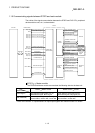
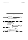
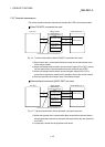
Installation and connection of master module and D75P2
Setting of master module and D75P2 (transmission speed, station number, etc.)
·
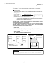
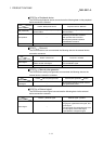
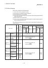
Data setting method
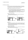
zero point return control