


12 - 48
MELSEC-
A
12 CONTROL AUXILIARY FUNCTIONS
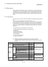
(2) Preparation
Note the details in the following table for preparation of the absolute position
detection system.
System component Details
1) Servo amplifier
(MR-H-A, MR-J2-A, MR-J2S-A)
Fit the battery (MR-BAT, A6BAT) to the servo amplifier.
Make the servo amplifier side absolute position detection
function valid.
For other details, refer to the servo amplifier side instruction
manual.
2) Servomotor
(HA- H -Y type)
Use the servomotor equipped with absolute position
detector.
For other details, refer to the servomotor side instruction
manual.
3) Detector cable
Add the connection of the battery power supply (BAT, LG
signals) to the wiring of the incremental detector cable.
For other details, refer to the cable side instruction manual.
4) Connection cable
Use the user-fabricated cable or following dedicated cable.
AD75C20SNH, AD75C20SNJ2
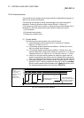
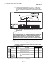
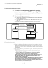
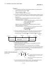
[2] Outline of absolute position detection data communication
As shown in the system block diagram of Fig. 12.32, the detector consists of the
encoder, which detects a position within one revolution in addition to the A/B/Z-phase
signals for position control during normal operation, and the cumulative revolution
counter that detects the number of revolutions.
This absolute position detection system always detects the absolute position of a
machine and stores it by battery backup, independently of whether the PLC system
power is ON or OFF. Therefore, once an initial zero point setting is made at the time of
machine installation, no zero point return at power-on will be required after that,
ensuring ease of restoration at an instantaneous power failure or emergency stop.
Backed up by the super capacitor in the detector, the absolute position data is retained
within the specified time if the cable is disconnected or broken.
D75P2
Servo amplifier
Pulse train
command
Zero point data
Backup at
power off
E
2
PROM memory
LS0
1X0
Within-one-
revolution
position
detection
LS
Number of
revolutions
detection
Servomotor
Within-one-revolution counter
(Detector)
1pulse/rev cumulative revolution
counter
Super capacitor
Battery
Current feed
value
Machine feed
value
Input
Output
Current
position
1X
Speed control
Position control
High-speed serial communication
A B Z
-phase signals
Fig. 12.32 Outline of absolute position restoration function